Introduction
Crystals are used in the majority of high-frequency electronics projects. And, that’s why it is essential to have a crystal tester. Without the right tool, testing the crystal would have been a difficult and time-consuming process. Unfortunately, commercial crystal testers are highly expensive; for this reason, here in this article we are making the “crystal tester circuit.”
The circuit is easier to make and requires very few electronic components. So, let’s give it a try!
What is a Crystal?
The term “crystal” is frequently used in electronics to refer to the quartz crystal or ceramic wafer that serves as the frequency-determining element and has electrodes attached to it. It is more properly known as a piezoelectric resonator. Crystals are also utilized in various sorts of electronic circuits, like crystal filters.
Hardware Required
| S.no | Component | Value | Qty |
|---|---|---|---|
| 1. | Transistors | BC547 | 2 |
| 2. | Diode | 1N4148 | 1 |
| 3. | LED | – | 1 |
| 4. | Push Switch | – | 1 |
| 5 | Ceramic Capacitor | 0.01uF, 22pF | 1,1 |
| 6. | Resistor | 270Ω, 2.2Ω, 100KΩ | 1,1,1 |
| 7. | Battery | 9v | 1 |
| 8. | 2-Pin Connector | – | 2 |
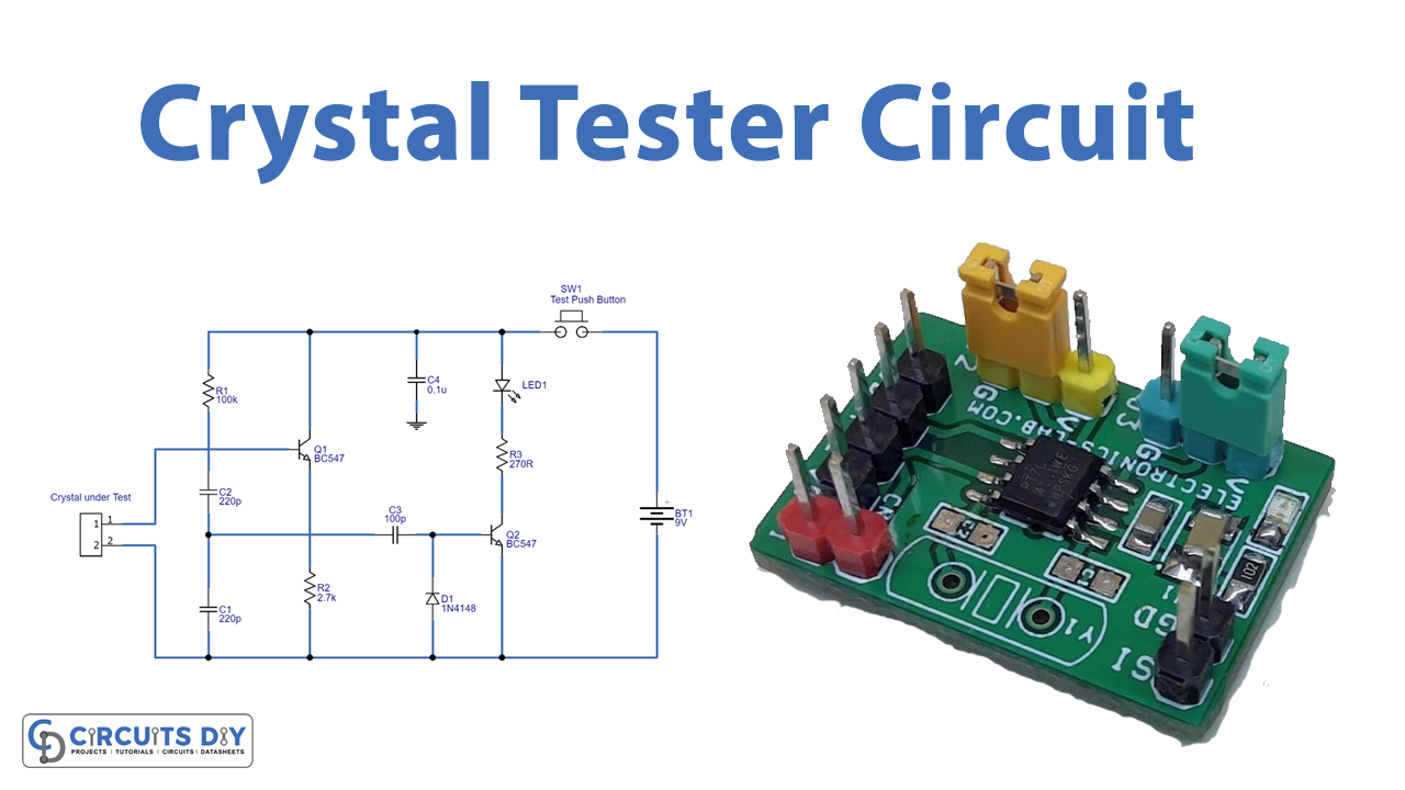
Circuit Diagram

Working Explanation
The base terminals of the two BC547 transistors that make up this Crystal Tester Circuit serve as a test terminal for the crystal. Together, the transistor Q1 and the crystal to be tested form a complete crystal oscillator. The DC voltage at the transistor Q2 base is high enough with an intact crystal to cause the transistor Q2 to conduct. Thus, the Q2 transistor drives LED1, and if the LED glows, the crystal being tested is functioning; if the LED is not glowing, the crystal may be damaged or faulty. This circuit can be powered by a 9-volt battery.
Application and Uses
- To determine whether or not a crystal element is functioning properly.
- To test the crystal in radio transmitters, radio controllers, and so forth.