Here we are demonstrating a very useful project of a contactless mains failure alarm circuit. this circuit will detect wirelessly the absence of AC mains voltage in the lines or alarms. When there will be no voltage the circuit will produce a sound of beep beep until the voltage in the mains is back.
The current consumption of this circuit is very low only 450µA on standby due to which the batteries will last for several months. And since we are using this circuit with batteries so it is portable and can be placed in a small enclosure with batteries inside. The antenna used in the circuit should be a thin hard 4-inches wire placed inside the enclosure to not come physically in contact with any main connection.

Hardware Components
The following components are required to make Main Power Failure Alarm Circuit
| S.no | Component | Value | Qty |
|---|---|---|---|
| 1. | Input Supply DC | 4.5-12V | 1 |
| 2. | IC | NE555 Timer | 1 |
| 3. | Opamp IC | LM358 | 1 |
| 4. | Antenna | 4-inches | 1 |
| 5. | Resistor | 470KΩ, 1KΩ, 10KΩ, 470Ω | 1, 2, 1, 1 |
| 6. | Transistor | 2N4403 | 1 |
| 7. | Ceramic Capacitor | 0.01µF | 1 |
| 8. | Electrolytic Capacitor | 10uF | 1 |
| 9. | Buzzer | – | 1 |
| 10. | Variable Resistor | 100KΩ, 1MΩ | 1, 1 |
| 11. | LED | – | 1 |
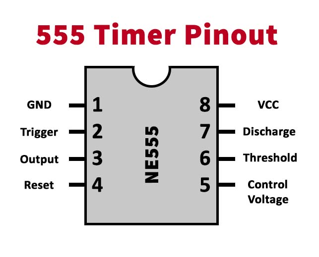
NE555 IC Pinout

For a detailed description of pinout, dimension features, and specifications download the datasheet of NE555 IC
LM358 Pinout

For a detailed description of pinout, dimension features, and specifications download the datasheet of LM358
Main Power Failure Alarm Circuit

Working Explanation
The operating voltage of this circuit is 4.5 to 12V. it is working around two ICs one of them is a dual voltage comparator IC LM358 and the other one is a 555 timer IC. around LM358 there is an EMF detector built and a beeper circuit is built around the 555 timer IC. the circuit will keep producing a beep beep sound and flashes LED light from the beeper circuit but when the AC voltage is detected by the antenna it will send a signal to the LM358 IC and the beeping sound will stop. The sensitivity of this circuit can be increased or decreased by a 1M variable resistor. Another variable resistor of 100K is used to adjust the speed of the flashing LED and beeps.


