Designing a PCB is an intricate process that requires the designer to deal with complex problems and issues. Throughout the design process, there are a lot of steps on which the operational success of the design hinges but none other more so than the accurate creation of the Gerber file. Gerber file accumulates for the entire design work in terms of machine code. So that the design instructions can be fed to the PCB manufacturing CNCs as accurately as possible. Accurate Gerber files are especially important for PCB Fab houses, as a single mistake could end up costing millions in terms of production and material resource loss. So, in today’s tutorial, we will take a closer look into some of the common Gerber file problems that occur in PCB designing and how to avoid them.
Gerber File
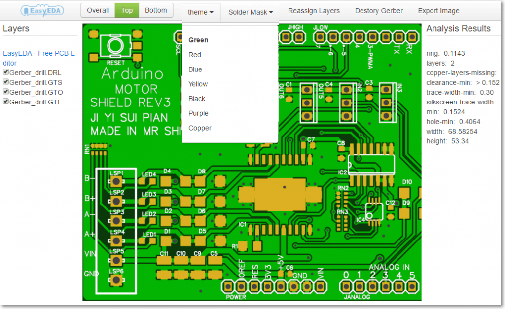
Gerber files are open ASCII vector format files that have info on each layer of your PCB design. Circuit board objects, like copper traces, vias, pads, solder mask, and silkscreen images, are all shown by a flash/draw code and defined by a series of vector coordinates. PCB manufacturers use these files to translate the details of your PCB design into the physical properties of the PCB.
Common Gerber File Problems and Their Solutions
1) Outmoded File Format
Always avoid generating Gerber files with 274D file format. The 274D Gerber format is completely obsolete with current PCB manufacturers. Most manufacturers in today’s design market accept either the 274X Gerber format or it’s updated version called the Gerber X2 format. This does not mean that your manufacturer will no longer accept the 274X Gerber format, as most PCB manufacturers are still working with it. Always check with your PCB manufacturer beforehand and verify what Gerber format do they accept.

2) Drill Format
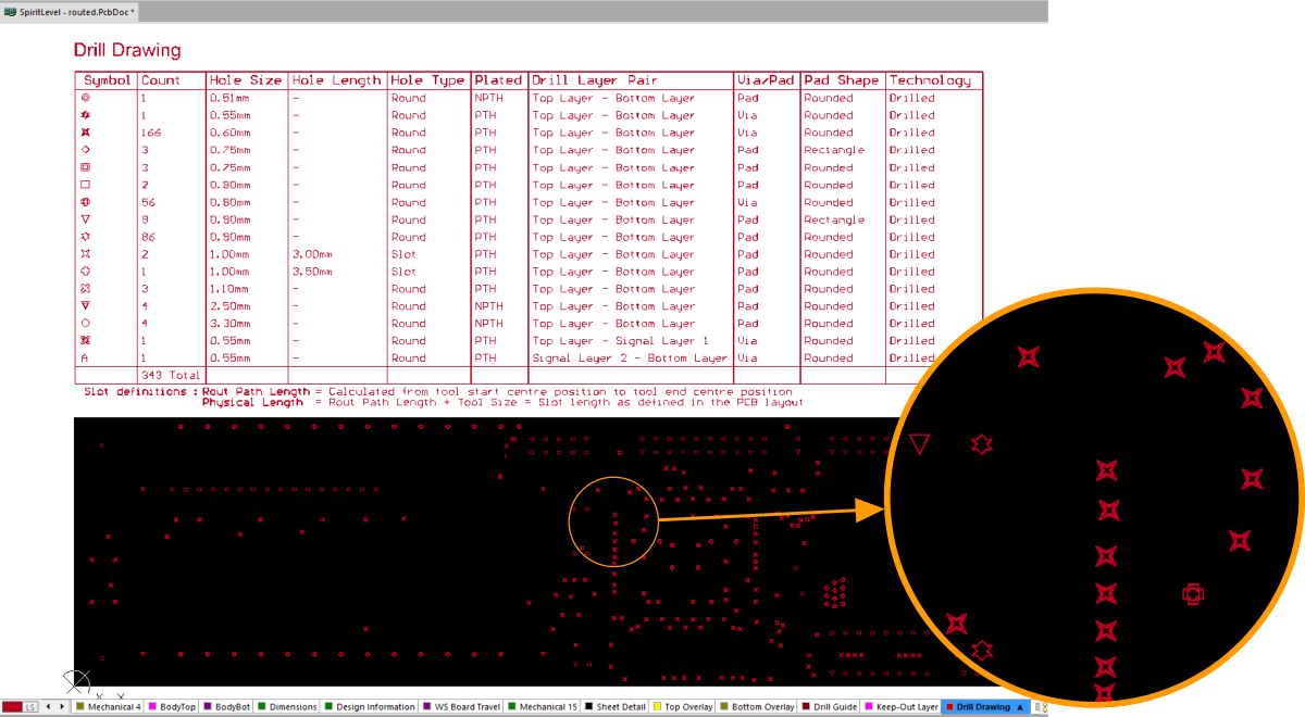
A number of times Drill files are provided without the correct file format. It becomes really frustrating for the manufacturer to import the Gerber file and the entire process is then chalked up to an awkward trial and error format. To resolve this, The header in the file should include information that clearly indicates the format. The proper format is called an NC Drill file.
3) No Fabrication Drawing
Always provide fabrication drawings to your manufacturer even if the Gerber viewer they use can design one. fabrication drawing provides useful information about the desired board details that are not contained within the Gerber files. In addition to displaying the overall dimensions of the board, they will identify any special cut outs or routing. They can also contain any notes related to the fabrication of the boards such as file names, material type, thickness, finish, etc.
4) Unregistered Board Layers
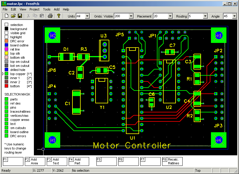
You should always have the Gerber files registered to a common data point. Some Gerber files have layers associated at a different datum alignment which then requires by hand alignment of the unregistered layers. This is easy to change but is an instance that requires additional time and opens the door for errors to happen.
5) Board Outline Not Included
It is imperative that you provide the Gerber files with the board outline clearly defined. It is one of the key pieces of information that the manufacturer needs in order to work on your design and the manufacturer will most probably put your PCB on hold until you provide the board outline. Providing a board outline is important as it defines the dimensions of the PCB board as per your requirement.
6) Unorganized File Labels
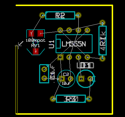
The file labels for each Gerber file should be in proper order and must be easy to interpret. Each PCB CAD software has its own way of exporting Gerber files. Any Gerber file exporting system is fine as long as it’s file label either makes obvious sense or provides the details of the file names and which layer they correspond to.


