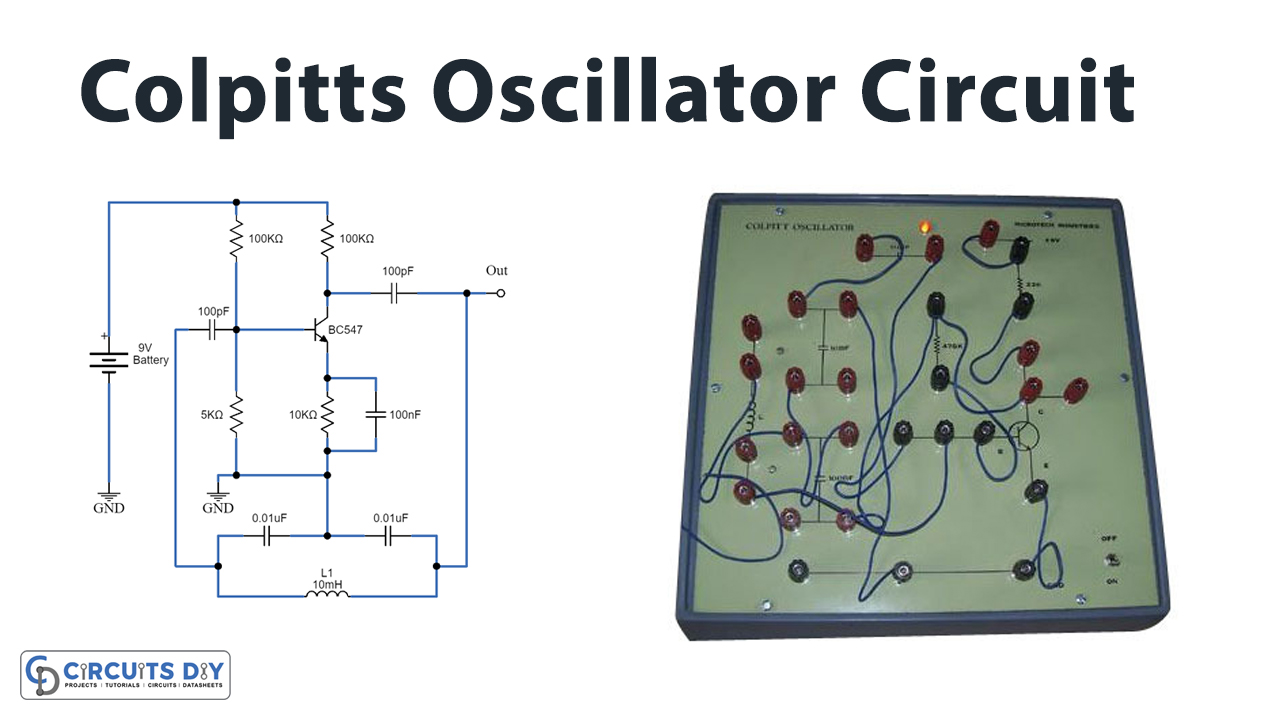
In this tutorial, we are going to make a “Colpitts Oscillator Circuit”.
It is difficult to provide individual power supply sources to each component in the circuit because most of the time when we are dealing with different electronic circuits and microprocessors or microcontrollers, they require a source of signal with a specific frequency and amplitude, therefore we use Oscillator circuits to provide different levels of signals to different circuit elements. An oscillator is a circuit that produces a continuous, repeated, alternating waveform without any input. Oscillators convert unidirectional current flow from a DC source into an alternating waveform that is of the desired frequency, as decided by its circuit components.
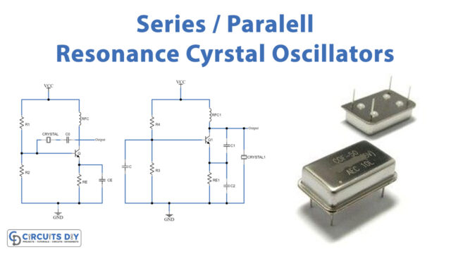
Here simple Colpitts oscillator circuit is designed to produce constant sinusoidal output. A Colpitts oscillator is a type of LC oscillator. Like other Oscillator circuits, the Colpitts oscillator also has the Tank circuit, Amplifier, and a feedback path. This circuit maintains positive feedback between the amplifier and tank circuit and also provides undamped oscillation at the output. The distinguishing feature of the Colpitts oscillator is that the feedback for the active device is taken from a voltage divider made of two capacitors in series across the inductor.
Hardware Components
The following components are required to make Colpitts Oscillator Circuit
| S.no | Component | Value | Qty |
|---|---|---|---|
| 1. | Transistor | BC547 | 1 |
| 2. | Resistor | 100KΩ, 5KΩ, 1KΩ, 10KΩ | 1,1,1,1 |
| 3. | Ceramic Capacitor | 0.01μF,100pF,100nF | 2,2,1 |
| 4. | Inductor | 10mH | 1 |
| 5. | Connecting Wires | – | 1 |
| 6. | Power Supply | 9V | 1 |
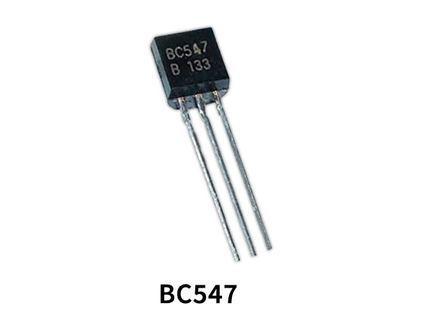
BC547 Pinout

For a detailed description of pinout, dimension features, and specifications download the datasheet of BC547
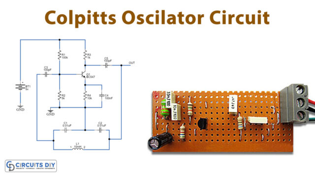
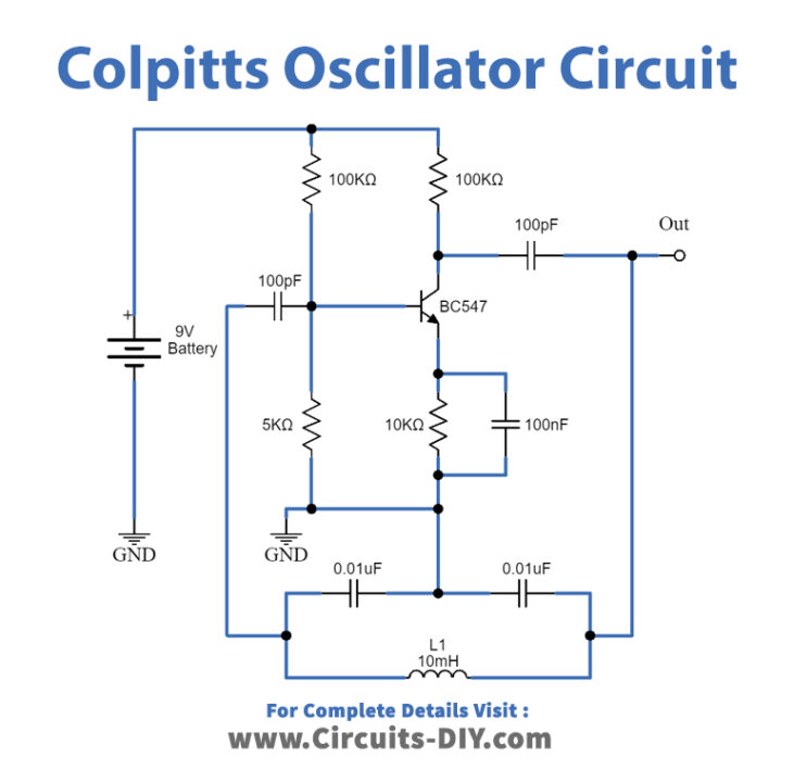
Colpitts Oscillator Circuit
Working Explanation
Generally, a Colpitts oscillator with a tank circuit is an inductor L connected parallel to the serial combination of tapped capacitors C1 and C2. Other components in the circuit, Transistor BC547 act as a common emitter amplifier which is biased using a voltage divider network. R1 and R2 Resistors provide bias to CB terminals and BE terminals. The feedback path between the collector and base terminal has a tank circuit in its path. Further, the capacitors C3 and C5 are the input and output decoupling capacitors while the emitter capacitor C4 is the bypass capacitor used to bypass the amplified AC signals.
as the power supply is switched ON, the transistor starts to conduct due to which the capacitors C1 and C2 get charged. On acquiring the maximum charge feasible, these capacitors start to discharge through coil L and so, initial oscillations are generated. Next, the inductor starts to discharge, which charges the capacitors once again. Likewise, the cycle continues, which gives rise to the oscillations in the tank circuit. the output of the amplifier appears across C1 and thus is in-phase with the tank circuit’s voltage Thus this amplified signal is applied to the tank circuit to meet out the losses during energy conversation between capacitors C1 and C2 and inductance L. On the other hand, the voltage feedback to the transistor is obtained across the capacitor C2, which means the feedback signal is out-of-phase with the voltage at the transistor by 180o. This is because the voltages developed across the capacitors C1 and C2 are opposite in polarity as the point where they join is grounded. The amount of feedback depends upon the value of capacitance C1 and C2. The transistor amplifier provides a 180º phase shift and the capacitor feedback provides another 180º phase shift. Hence totally there will be a phase shift of 360º which provides positive feedback. Therefore, continuous undamped oscillations are generated, these oscillators can be tuned either by varying their inductance or the capacitance. However, the variation of L does not yield a smooth variation, they are usually tuned by varying the capacitances.
Colpitts Oscillator circuit formula
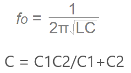
L = Inductor value of L1.
C = Total value of capacitors C1 and C2 connected in series.
Applications
The Colpitts oscillators are seldom preferred in applications wherein the frequency varies but are more popular as fixed frequency oscillators due to their simple design. The Colpitts oscillator circuit is used in signal generators and used in superheterodyne radio receivers as local oscillators and many low-cost oscillators.