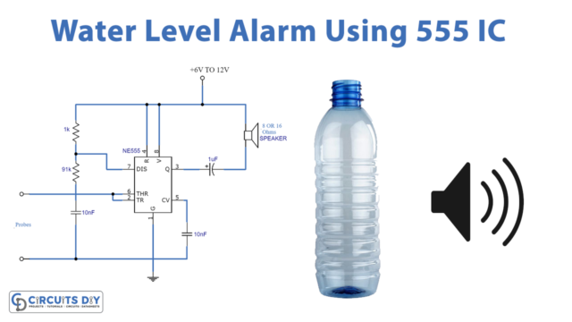
A charge pump is a kind of converter that uses energetic charge storage condensers to increase or decrease voltage. Charge-pump circuits, while being electrically simple circuits, are capable of high efficiencies, often as high as 90–95 percent.
You have a low-voltage supply line, assume 3.3V, so you want anything that requires 5V to run. This is a tough call particularly if it includes batteries. A turn mode converter, more accurately a boost converter, is the only obvious path forward.
Hardware Components
The following components are required to make Charge Pump Circuit
| S.no | Component | Value | Qty |
|---|---|---|---|
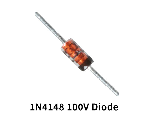
| 1. | Diodes | 1N4148W | 6 |
| 2. | Capacitors | 10uF, 100uF | 5, 1 |
| 3. | Power Supply | – | 1 |
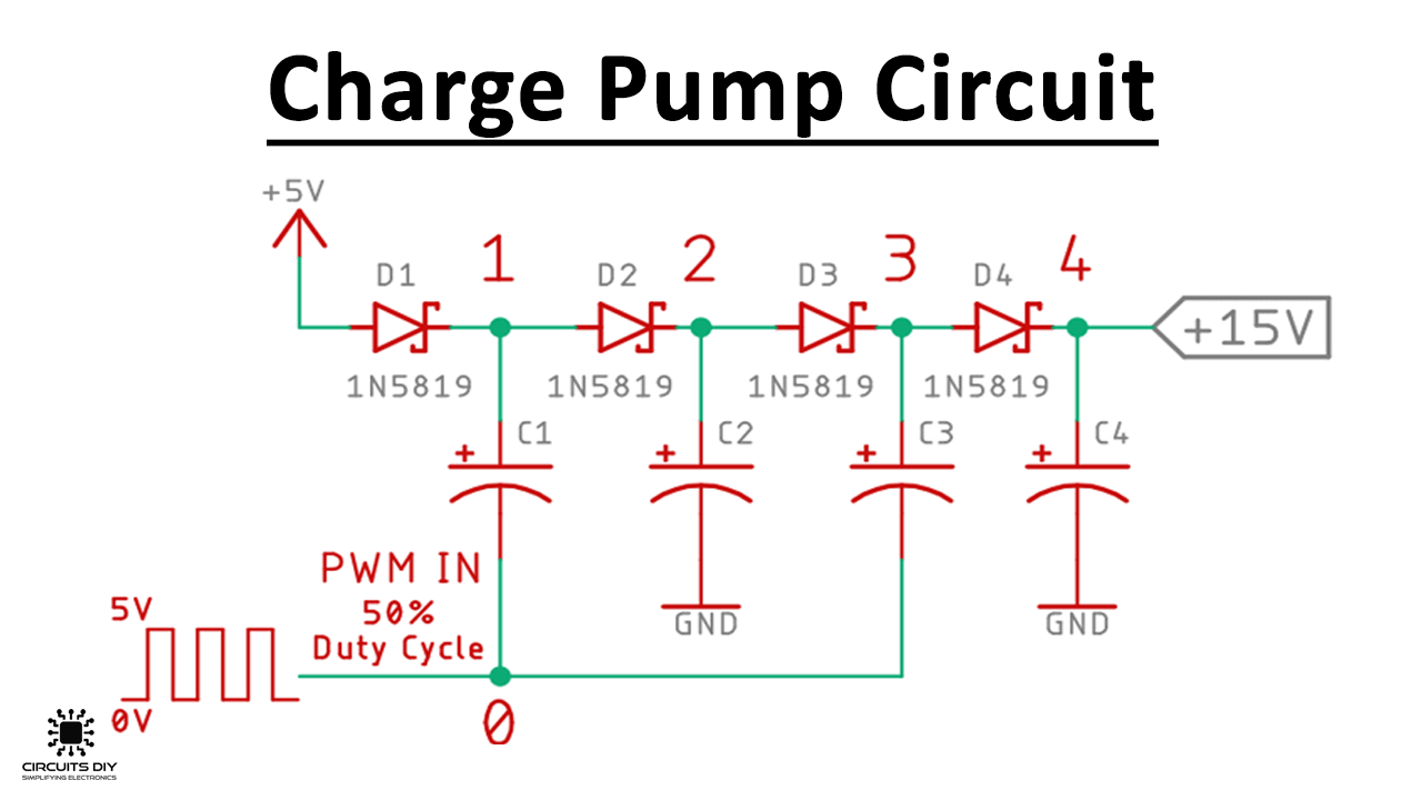
Charge Pump Circuit
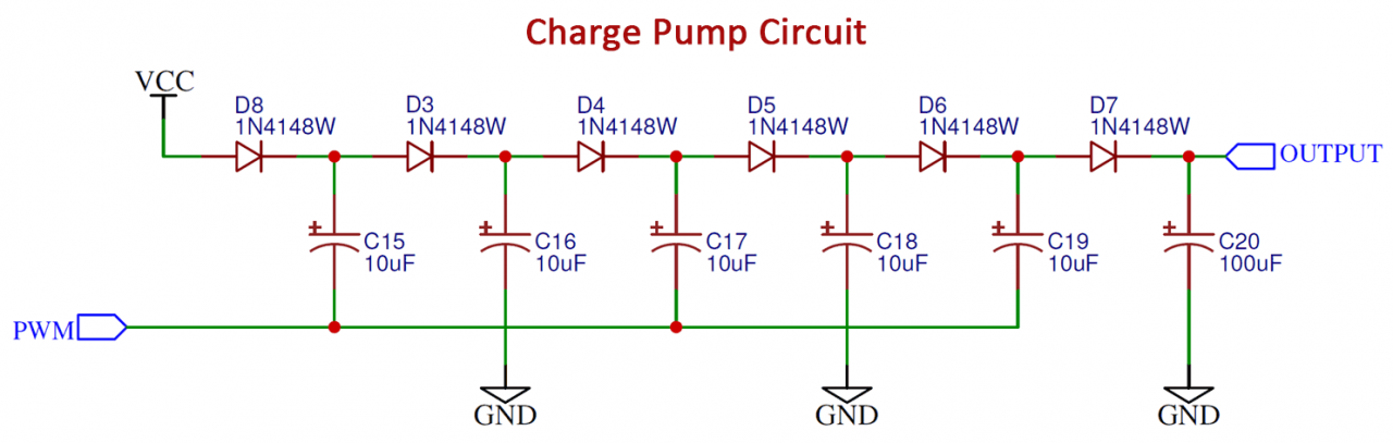
Working Explanation
The easiest way to explain that is to picture the situation below. Using a 9V battery, you charge a capacitor, so the voltage around the condenser is also 9V. You then take another condenser and charge it up to 9V too. Link the two condensers now in series and calculate the voltage between them-18V.
This is the basic concept of the load pump process-take two condensers, Load them individually and then bring them into order, even though the rearrangement is performed electronically in a real charge pump. Of course, this is not limited to just two condensers, successive stages can be cascaded to achieve higher output voltages.
Application and Uses
- Bipolarity source for the op-amps in a circuit where there is just one voltage. Op-amps do not use a huge amount of current and it’s a great fit.
- It is also used by gate drivers.