CD4541 programmable timer is a part of the CD4000 IC series. It consists of a 16 – stage binary counter, an output control logic, and a special power-on reset circuit. The special features of the power-on reset circuit are first, no additional static power consumption, and second, the part functions across the full voltage range (3V–15V) whether power-on reset is enabled or disabled. The CD4541 has a wide array of features such as high noise immunity and a wide range of operative conditions. It also offers ESD protection and thermal overload compensation.
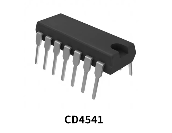
Programmable Timer
Programmable Timers are simple circuits that offer measurement, display and control in applications that contain variables. They can operate with a single input or, in some cases, a pair of signals. Programmable timers are usually electronic and use digital displays, precise digital set-ability, high accuracy, and fast reset times.
Oscillator Circuit?
Oscillator circuits produce a continuous, repetitive, alternating waveform without any input. An Oscillators basically converts unidirectional current flow from a DC source into an alternating waveform which is of the desired frequency with respect to the circuit components.
CD4541 Key Features
- Available division ratios 28, 210, 213, or 216
- Increments on positive edge clock transitions
- Built-in low power RC oscillator (±2% accuracy over temperature range and ±10% supply and ±3% over processing @ < 10 kHz)
- Oscillator frequency range ≈ DC to 100 kHz
- Oscillator may be bypassed if external clock is available (apply external clock to pin 3)
- Automatic reset initializes all counters when power turns on
- External master reset totally independent of automatic reset operation
- Operates at 2n frequency divider or single transition timer
- Q/Q select provides output logic level flexibility
- Reset (auto or master) disables oscillator during resetting to provide no active power dissipation
CD4541 Pinout
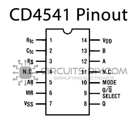
| Pin No | Pin Name | Description |
|---|---|---|
| 1 | RTC | Resistor Pin |
| 2 | CTC | Capacitor Pin |
| 3 | RS | Reset Pin/RS flip-flop Pin |
| 4 | NC | Not Connected |
| 5 | AR | Auto Reset Pin |
| 6 | MR | Master Reset Pulse |
| 7 | VSS | Source Supply |
| 8 | OUTPUT | Output Pin |
| 9 | Q/Q’ | Select Output Control |
| 10 | MODE | Mode Select Pin |
| 11 | NC | Not Connected |
| 12 | A | Input Pin A |
| 13 | B | Input Pin B |
| 14 | VDD | Drain supply |
Application
- Programmable timer ICs can be used in creating electronic timers for various AC/DC appliances such as washing machines, water pumping stations, etc.
CD4541 Datasheet
You can download the datasheet for CD4541 Oscillator/Programmable Timer from the link given below:
See Also: 74LS258 Quad 2 To 1 Data Selectors/Multiplexers IC With 3-State Outputs | 74LS221 Dual Monostable Multivibrator IC With Schmitt Trigger|Datasheet | 74LS170 4×4 Register File Open-Collector IC | Datasheet


Comments are closed.