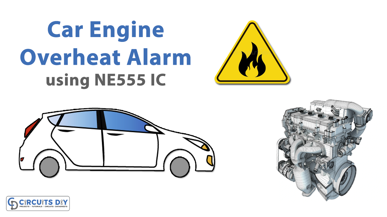
The automobile is a recombination of many things, like the transmission, AC, radiator, speedometer, level monitor and the list goes on. But one of the most critical things is the engine temperature; if left unchecked will ultimately lead to an engine seizure due to expansion of the metal body and causes it to come to a halt. Not only does this halt the engine but causes micro-fractures leading to reduced engine life.
So in this article, we will be making a circuitry to alert the user if the engine has reached its upper-temperature limit and sound an alarm to inform the driver to take action, such as stopping the car and checking the radiator fluid.

Hardware Components:
The following components are required to make the Car Overheat Alarm Circuit
| S.no | Component | Value | Qty |
|---|---|---|---|
| 1. | DC Supply | 5V to 15V | 1 |
| 2. | IC | LM358 | 1 |
| 3. | LED | 5mm | 1 |
| 4. | Buzzer | – | 1 |
| 5. | IC | NE555 Timer | 1 |
| 6. | Resistors | 1k,10k | 2, 2 |
| 7. | Potentiometer | 100k | 2 |
| 8. | Ceramic Capacitor | 0.01uF | 1 |
| 9. | Electrolytic Capacitor | 10uF | 1 |
| 10. | Transistor | 2N4403 | 1 |
| 11. | NTC Thermistor | 10K | 1 |
555 IC Pinout

For a detailed description of pinout, dimension features, and specifications download the datasheet of 555 Timer
Car Overheat Alarm Circuit

Working Explanation:
So basically the main player here is the LM358 comparator. Basically, it compares the voltage across the NTC and the Potentiometer Pot. If the resistance across the NTC is larger the comparator will generate a high output. The output will trigger the transistor 2N4403, which will turn on the buzzer and the LED.
Applications & Uses:
- In automobiles with radiators.
- Usage for your water geyser.


