Introduction
Are you looking for an added layer of security for your home or business? Imagine a world where your home and business are protected by a state-of-the-art security system that can detect even the slightest movement. With a capacitive proximity sensor alarm circuit, that world is a reality. This technology uses electrical capacitance to detect the presence of nearby objects, triggering an alarm when something or someone comes within a specific range. It’s a subtle yet highly effective way to deter intruders and protect your property.
So, are you ready to take the reins of your home security and build a circuit that will protect you and your loved ones? Look no further than this tutorial that will guide you through creating a capacitive proximity sensor alarm circuit. Don’t wait any longer; grab your tools, and let’s dive into the world of circuit building together!
What is Capacitive Proximity Sensor?
Capacitive proximity sensors are devices that do not need physical contact and can detect the presence or absence of nearly any object, irrespective of the material it is made of. They make use of the electrical property of capacitance and the change in capacitance that occurs due to a change in the electrical field that surrounds the active face of the sensor.
Hardware Required
You will require the following hardware for Capacitive Proximity Sensor Alarm Circuit.
| S.no | Component | Value | Qty |
|---|---|---|---|
| 1. | Relay | 12 V 1 RT | 1 |
| 2. | Transistor | BC107, BC517 | 1, 1 |
| 3. | Capacitor | 10-60 pF, 10 nF polyesters, 680 pF ceramic, 10 nF polyester, 100 μF electrolytic, 10 nF polyester | 1 |
| 4. | Resistor | 10k, 470k, 3.3k, 1k | 1 |
| 5. | Diode | 1N4148, 1N1448, 1N4007 | 3 |
| 6. | Coil | self 1 mH | 1 |
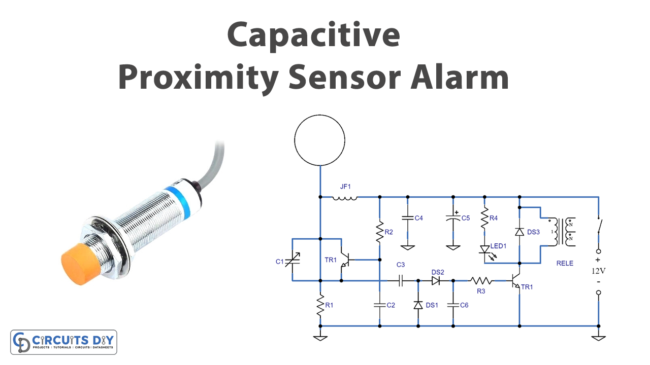
Circuit Diagram

Testing
- Start by connecting the circuit to a power source and ensuring the relay is in the off position.
- Place a metal dish or a piece of the printed circuit board or sheet metal near the sensor and observe if the relay switches on.
- Adjust the value of the variable capacitor, C1, to change the oscillator’s frequency and test the circuit again.
- Test the circuit’s sensitivity by moving the metal dish closer or further from the sensor and observing if the relay switches on or off accordingly.
- Finally, test the circuit with a person approaching and touching the metal dish and see if the circuit turns off the relay.
Working Explanation
The capacitive proximity sensor alarm circuit is a simple circuit that uses a transistor as an oscillator to operate a relay. The circuit works by using the transistor as an HF oscillator, whose frequency is determined by the JAF1 choke and the parasitic capacitance of a metal dish connected to its collector. The high-frequency signal is then extracted from the emitter through the capacitor C3 and sent to a pair of diodes, DS1 and DS2, which convert it into a positive DC voltage. This voltage is then sent to the base of a second transistor, TR2, which in turn powers the relay.
When an object comes near or touches the sensor dish, the oscillator stops, and the base of TR2 no longer receives positive voltage, which causes the relay to switch OFF. To adjust the operating position of the oscillator, an adjustable capacitor, C1, is placed between the collector and emitter of TR1. A diode, DL1, is also connected in parallel with the relay winding to indicate when the relay is off.
The circuit operates at a frequency of approximately 500 kHz due to the 1 mH JAF1 choke. However, by adjusting the value of this component, the circuit can also work at different frequencies.
Final Words
In this tutorial, we have covered building a capacitive proximity sensor alarm circuit, including the materials needed, step-by-step instructions, and key concepts to keep in mind. We hope you have found this tutorial informative and easy to follow. Feel free to ask any questions in the comment section!


