Introduction
Your property and assets are safest when they are protected by a security system. If there is a danger of getting detected, thieves are less inclined to harm your property. A great wireless home security system can both safeguard our homes and help us in our daily lives. Keep this in mind, in this article, we are making a Buzzer Alarm System With the Help Of Arduino
The alarm systems with buzzers are often utilized as sound alarms. They are frequently employed to provide an auditory cue in reaction to an action or occurrence.
What is Buzzer Alarm System?
An alarm system is a device that warns people about highly unsafe situations at the workplace or home. A buzzer alarm system is intended to warn us of an emergency by sending an auditory signal. Hence it uses a buzzer to create a sound.
Hardware Components
You will require the following hardware for Buzzer Alarm System.
| S.no | Component | Value | Qty |
|---|---|---|---|
| 1. | Arduino UNO | – | 1 |
| 2. | PIR Motion Sensor | HC-SR501 | 1 |
| 3. | Buzzer | – | 1 |
| 4. | LED | – | 1 |
| 5. | Button | 12mm | 1 |
| 6. | Resistor | 1KΩ, 330Ω | 1, 1 |
| 7. | Breadboard | – | 1 |
| 8. | Jumper Wires | – | 1 |
Steps for Making a Buzzer Alarm System
To make this Buzzer Alarm System, you need Arduino, the above-defined motion sensor, and a few simple electronic components. After that, you need to follow the following steps:
Schematic
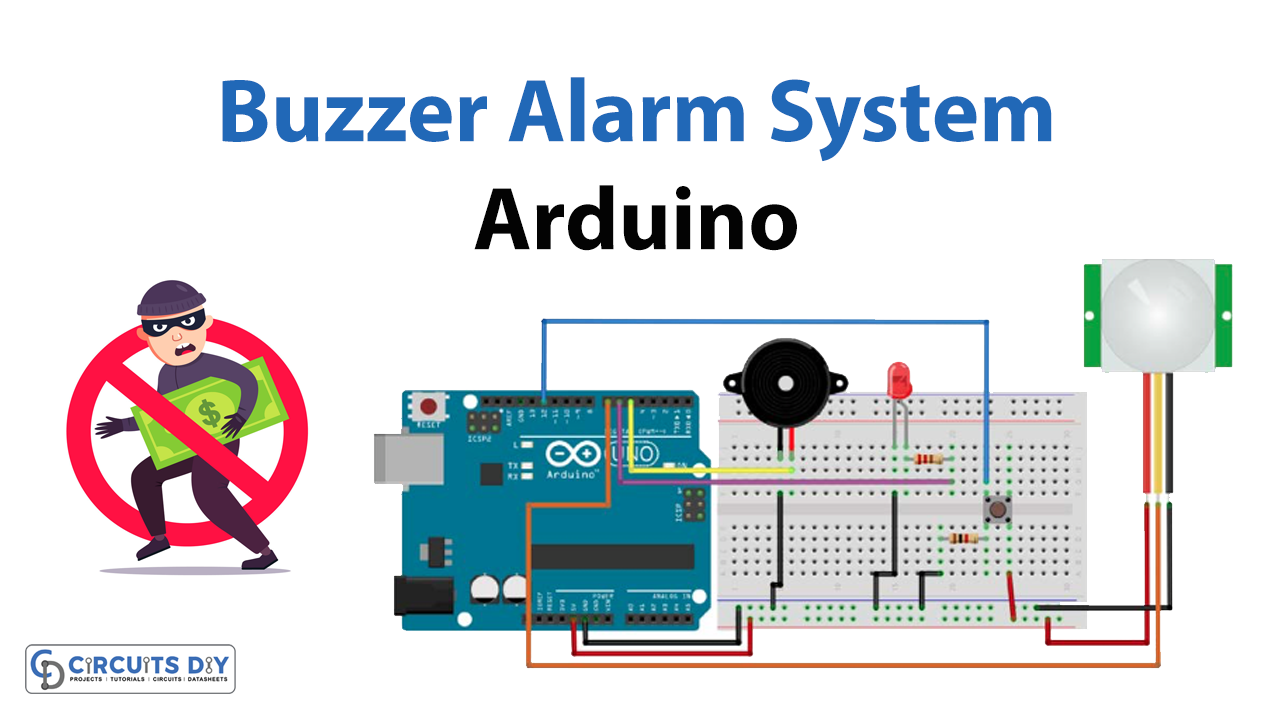
Make connections according to the circuit diagram given below.
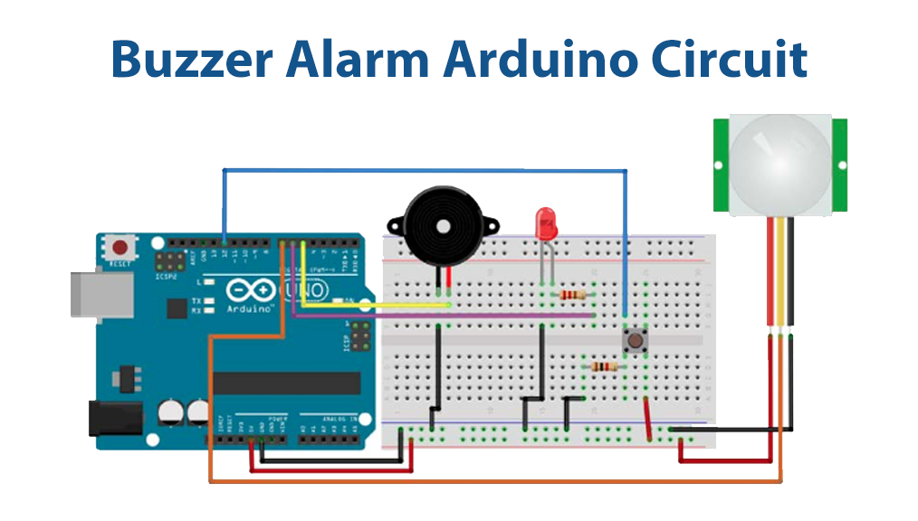
Wiring / Connections
| Arduino | PIR Motion Sensor | Buzzer | LED |
|---|---|---|---|
| 5V | VCC | ||
| GND | GND | -ve | -ve |
| D7 | OUT | ||
| D6 | +ve | ||
| D5 | +ve with Resistor 1K |
Installing Arduino IDE
First, you need to install Arduino IDE Software from its official website Arduino. Here is a simple step-by-step guide on “How to install Arduino IDE“.
Code
Now copy the following code and upload it to Arduino IDE Software.
// Declaring Pins
const int buzzerPin = 5;
const int ledPin = 6;
const int motionPin = 7;
const int buttonPin = 12;

// Setting Buzzer mode to False
boolean buzzer_mode = false;

// For LED
int ledState = LOW;
long previousMillis = 0;
long interval = 100;  // Interval at which LED blinks

void setup()
{
  //The Following are our output
  pinMode(ledPin,OUTPUT);
  pinMode(buzzerPin,OUTPUT);

  //Button is our Input
  pinMode(buttonPin, INPUT);

  // Wait before starting the alarm
  delay(5000);
}

void loop()
{
  // To chech whether the motion is detected or not
  if (digitalRead(motionPin)) {
    buzzer_mode = true;
  }

  // If alarm mode is on,blink our LED
  if (buzzer_mode){
    unsigned long currentMillis = millis();
    if(currentMillis - previousMillis > interval) {
      previousMillis = currentMillis;
      if (ledState == LOW)
        ledState = HIGH;
      else
        ledState = LOW;
    // Switch the LED
    digitalWrite(ledPin, ledState);
    }
    tone(buzzerPin,1000);
  }

  // If alarm is off
  if (buzzer_mode == false) {

    // No tone & LED off
    noTone(buzzerPin);
    digitalWrite(ledPin, LOW);
  }

  // If our button is pressed Switch off ringing and Setup
  int button_state = digitalRead(buttonPin);
  if (button_state) {buzzer_mode = false;}
}
Let’s Test It
The circuit has now become complete. After you Upload the code into is now time to test the circuit. Power up the Arduino and analyze the Serial Monitor results. Place something in front of the sensor and you would hear the buzzer sound.
Working Explanation
Let’s first dig into the code:
- First, we define and name the pins of Arduino that are connected to the sensor. We also define some useful variables.
- In the void setup, we define the state of pins; i.e, either input or output.
- In the void loop, the main code runs. This turns on an LED and buzzer when detected any motion. However, once the switch is pressed, the setup is switched off.
The PIR Sensor is made up of two slots, both of which are composed of IR Sensitive materials. When there is no movement in the vicinity of the sensor, both slots in the Sensor detect the same quantity of infrared radiation. When there is movement in front of the sensor, one of the slots interprets the radiation first, and the differential output between the two slots goes positive. A motion is identified based on this output
Applications
- Home and office automation
- Intruder alarms; etc
Conclusion.
We hope you have found this Buzzer Alarm System With the Help Of Arduino Circuit very useful. If you feel any difficulty in making it feel free to ask anything in the comment section.


