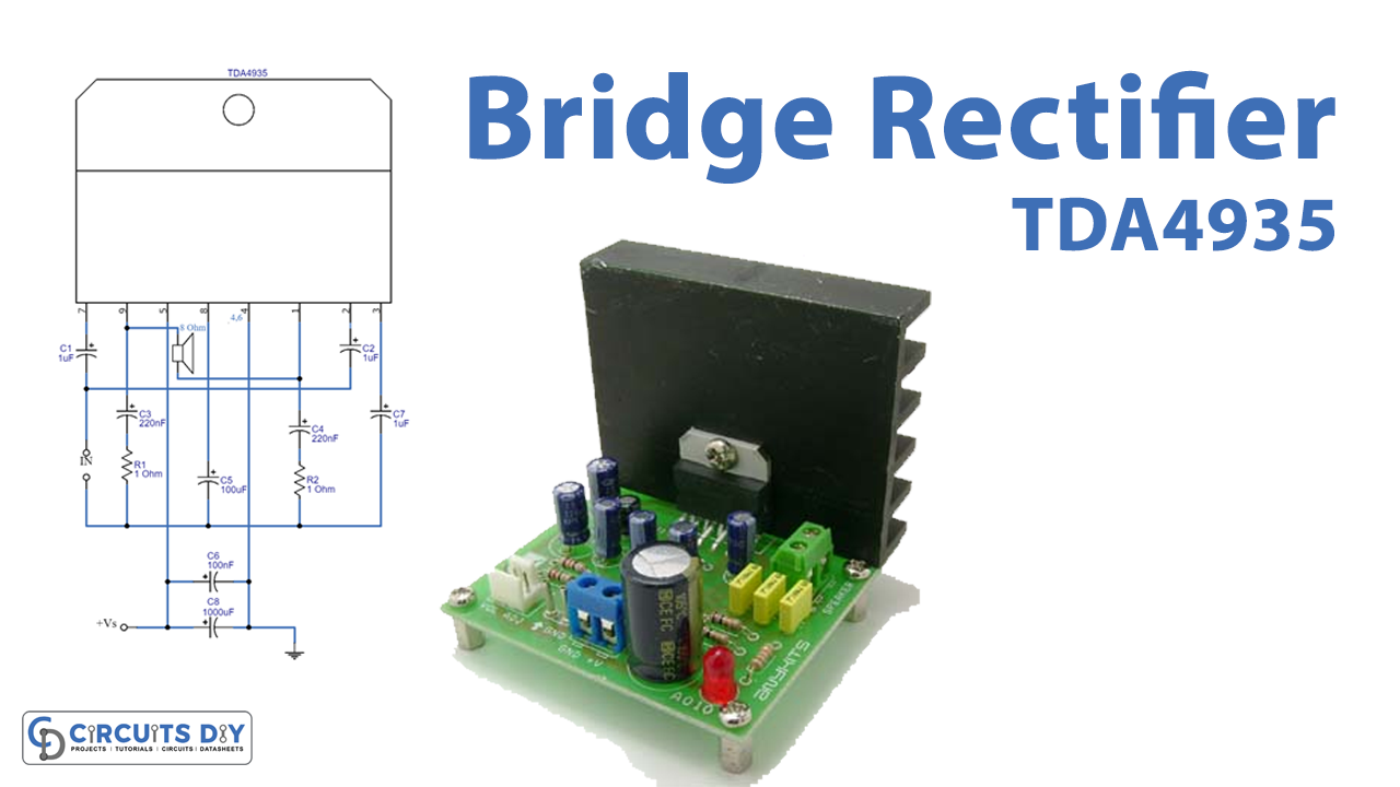
Introduction to Bridge Amplifier
To increase the output power of any signal or a circuit, a bridge amplifier gets utilized. Basically, it’s a method to combine two channels into a channel having twice the voltage. Practically, designers bridge four channels into two channels or two channels into a channel. Moreover, the speaker gets wired between the output of the amplifiers used in the circuits. Most of the bridge amplifiers used the opamps in their opposite polarities and therefore the circuits reduce the cost of DC block capacitors. Also, it saves space.
To make the circuit Bridge Amplifier using TDA4935, make sure to use the PCB Board of greater quality. Since the circuit uses the IC that dissipates heat. Therefore, it is preferable to utilize heat sinks in the circuit. further, you can use any voltage supply in the range of 8V to 30V.
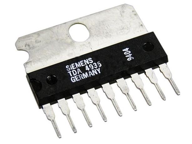
Features of TDA4935
- It has a wide supply voltage range from 8 to 30 V.
- The temperature storage range is from -40 degrees to 145 degrees.
- Thermal resistance is about 4K/w.
- It requires minimum external components.
Hardware Required
| S.no | Component | Value | Qty |
|---|---|---|---|
| 1. | PCB Board | – | 1 |
| 2. | IC | TDA4935 | 1 |
| 3. | Resistors | 1Ohms | 2 |
| 4. | Ceramic Capacitors | 1uF, 100nF, 220nF | 3, 1, 2 |
| 5. | Polar Capacitors | 100uF, 1000uF | 1, 1 |
| 6. | Speaker | 8 Ohm | 1 |
| 7. | Power Supply | 8 to 30V | 1 |
Circuit Diagram
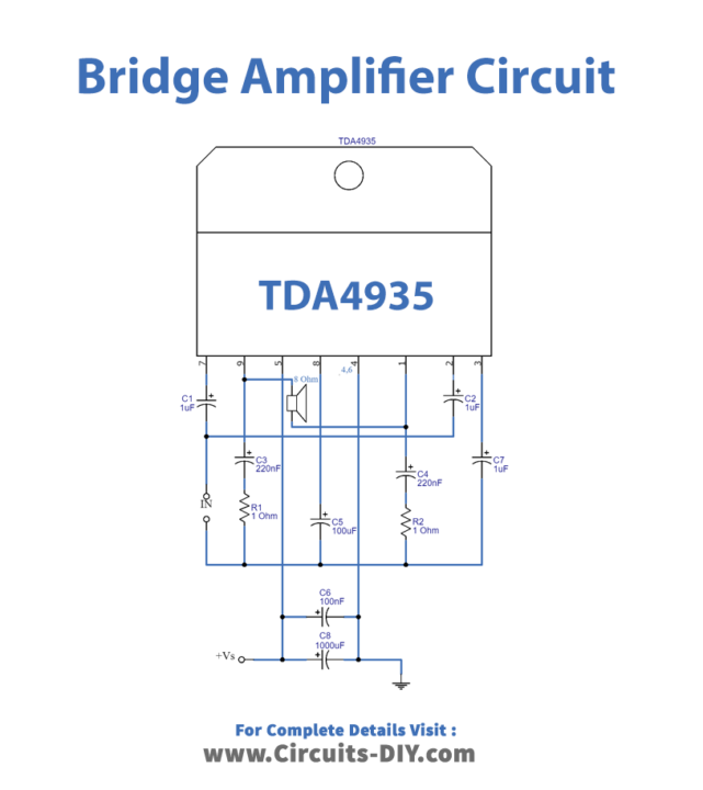
Working Explanation
TDA 4935 can be wired in stereo or in bridge mode. In stereo mode, it delivers 15watts of power. While in the bridge mode it delivers 30watts of power. The circuit comprises very few external components like polyester capacitors, C1, C2, and C8. Also, it has a ceramic capacitor, C4, C3, and C6. While there are also electrolytic capacitors like C5 and C9 in the circuit. the IC is connected in the class B mode configuration. Hence, work in the same way.
Application and Uses
- It can be used in any amplifier circuit that needs high output power at load.

