In this tutorial, we are going to make a “Boost Converter Circuit Using MC34063 IC”. We’ve all come across pesky situations where we need a slightly higher voltage than our power supplies can provide. We need 12 volts but have only a 9-volt battery. Or maybe we have a 3.3V supply when our chip needs 5V. That too, in most cases, the current draw is quite decent, we can achieve it by boosting the converter.
A boost converter is a DC-to-DC power converter that steps up voltage while stepping down current from its input supply to its output load. It is a class of switched-mode power supply containing at least one semiconductor a diode and at least one energy storage element: a capacitor, inductor, or the two in combination. To reduce voltage ripple, filters made of capacitors sometimes in combination with inductors are normally added to such a converter’s output load-side filter and input supply-side filter. Boost converters are highly nonlinear systems and a wide variety of linear and nonlinear control techniques for achieving good voltage regulation with large load variations have been explored.
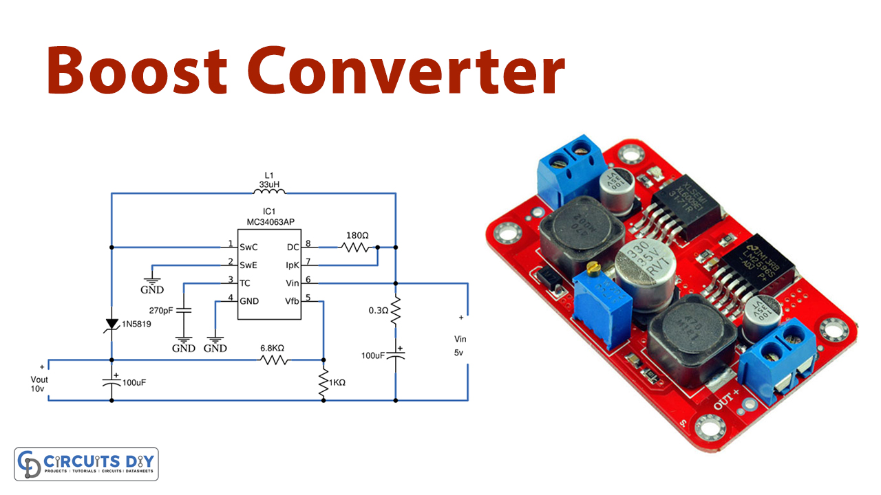
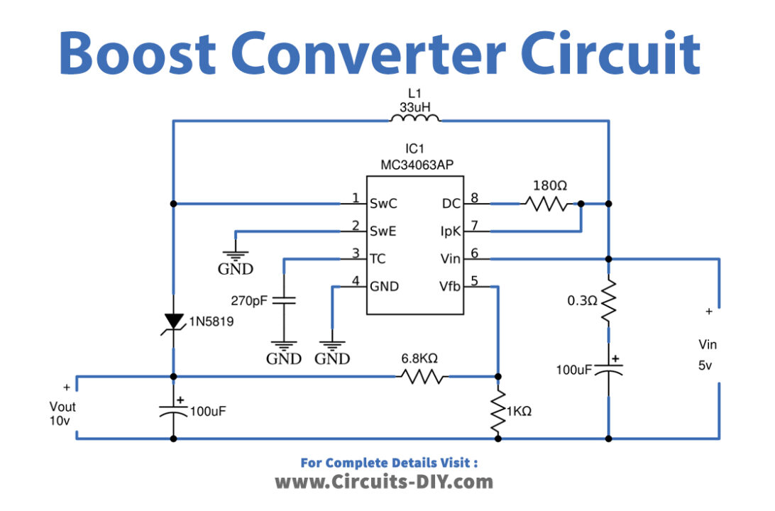
We designed a boost Converter Circuit Using MC34063 IC with a few external components and this IC is suitable for compact DC/DC to boost converter circuits, it contains all the primary circuitry needed for building simple DC-DC converters. The following Circuit is designed to boost Input voltage from 5V to 10V using a single power supply source.
Hardware Components
The following components are required to make the Boost Converter Circuit
| S.no | Component | Value | Qty |
|---|---|---|---|
| 1. | IC | MC34063AP | 1 |
| 2. | Schottky diode | 1N5819 | 1 |
| 3. | Inductor | 33µH | 1 |
| 4. | Electrolyte Capacitor | 100µF | 2 |
| 5. | Resistor | 0.3Ω, 1KΩ, 6.8KΩ, 180Ω | 1,1,1,1 |
| 6. | Ceramic Capacitor | 270pF | 1 |
| 7. | Power Supply | 5V | 1 |
MC34063AP Pinout
For a detailed description of pinout, dimension features, and specifications download the datasheet of MC34063AP
Boost Converter Circuit
Working Explanation
First, connect every component as near as possible to the IC MC34063. IC MC34063 is placed as a DC-DC Boost converter, here the 5v is applied as the input voltage to the circuit which can be boosted to around 10 Volt. By using the internal temperature compensated reference, a comparator, an oscillator (100KHz), a PWM controller with active current limiting, a driver, and a high current output switch this IC MC34063 can provide the Specific output required for your design. After connecting all components in the circuit calculate the output voltage by using the following formula.
Vout = 1.25(1+ (R2 / R1))
The desired output voltage can be generated by changing the values of R1 and R2. Due to the inductor value and specification, the practical output voltage may vary slightly. And take it as a theoretical output voltage range and apply bias to the circuit and check the output voltage and compare both. So, this is how this small circuit can be used variable output DC-DC converter.
Applications
This boost converter circuit is most suitable to drive or bias output actuators in the microcontroller or microprocessor-based design.


