In this tutorial, we are making a Battery High Low Alarm For Multiple Batteries. Usually, with batteries, there is an issue of overcharging or deep discharging. An alarm circuit for the indication of battery level always comes in handy during these situations. This circuit is adjustable and can monitor any type of battery having voltage ranging from 6V to 24V. It provides a beeping sound and blinks an LED when the battery voltage is low or high from the preset values.
This circuit is using two ICs. The first one is an operational amplifier IC, LM358. This IC comprises two op-amps and has 8 pins. It is usually used in detector circuits, therefore we have used it to detect the battery level of the Batteries. The second IC is one of the most famous ICs in the world of electronics i.e., 555 timer IC. This IC has a wide range of applications. It provides time delays or also works as an oscillator. It has three modes of operation i.e., monostable, astable, and bistable. In our circuit, it is working as an astable multivibrator.

Hardware Components
The following components are required to make Battery Alarm Circuit
| S.no | Component | Value | Quantity |
|---|---|---|---|
| 1. | IC | LM358, NE555 Timer | 1, 1 |
| 2. | LED | – | 4 |
| 3. | Phototransistor | PC817 | 2 |
| 4. | Diode | 1N4148 | 2 |
| 5. | Zener diode | 3V | 1 |
| 7. | Potentiometer | 10K, 100K | 2, 1 |
| 8. | Resistor | 10K, 470R, 470 ohms, 1K | 2, 4, 1, 1 |
| 9. | Capacitor | 10uF, 0.01uF | 1, 1 |
| 10. | Piezo buzzer | – | 1 |
| 11. | Transistor | 2N3906 | 1 |
| 12. | Dc Supply | 6-24V |
NE555 IC Pinout

For a detailed description of pinout, dimension features, and specifications download the datasheet of 555 Timer
LM358 Pinout
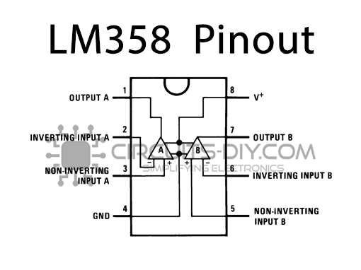
For a detailed description of pinout, dimension features, and specifications download the datasheet of LM358
Battery Alarm Circuit

Working Explanation
IC1 LM358 is wired as a voltage monitor in this circuit. The value of the desired minimum and maximum voltage can be selected with the two 10K variable resistors. VR1 and VR2 are used to set the desired high and low voltage respectively on which you want to get indicated.
Phototransistors along with an LED are used between these two ICs. When the IC1 will detect the high/low voltage of the battery it will send the output which lights the LEDs at their respective outputs.
This light will be sensed by the phototransistor and it will send an input signal to the 555 timer IC. There is a 100K pot used with the 555 timer IC, which will adjust the frequency of the oscillations of the IC. With the help of this, the flashing speed of the LED and the buzzer frequency can be adjusted.


