Computers and computing devices have integral importance in today’s life. From performing complex industrial process control operations to running simple games, computing devices play a major role in our everyday life and dealings. Out of a plethora of operations, the most important operation a computing system has to perform is performing logical operations by utilizing hardware resources like Integrated Circuits software technologies & electronic circuits. But in order to understand how these integrated circuits and peripheral hardware resources integrate and communicate with each other, we must have a clear understanding of the Boolean Logic. Every computational operation carried out by a computing device conforms to the laws and principles as defined in Boolean Logic. So in this tutorial, we will go over the Basic Digital Logic Gates Used In Digital Electronics.
What are Basic Digital Logic Gates?
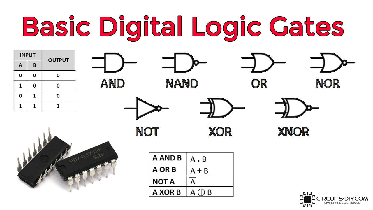
Digital logic gates are the basic building blocks of any digital switching circuit. The input and output relation of a logic gate is based on a certain relationship. Throughout history, logic gates have been implemented using various configurations such as the early RTL (Resistor – Transistor Logic), DTL (Diode – transistor logic), and currently, in use TTL (Transistor-Transistor Logic) which uses PMOS & NMOS CMOS technology to implement boolean functions and logical gates. Logic gates have a wide array of uses such as microprocessors, microcontrollers, embedded system applications, and electronic/electrical circuits.
Classification Digital Logic Gates
There are seven types of logic gates
Buffer Gate
A buffer gate is a basic digital logic gate that translates its input, unchanged, to its output. The behavior of a Buffer gate is the opposite of a NOT gate. The main purpose of a buffer gate is to regenerate the input signal, usually using a strong high and a strong low. A buffer has one input and one output; its output signal is always equal to its input signal.
Buffer Gate Symbol

To Buy Buffer gate ICs at a ridiculously good price, please check out the amazon product link provided here.
Truth Table

Boolean Representation
A=Y Where A is input & Y is output.
Here, the truth table and Boolean representation indicate that the output of the buffer gate will remain high as long as the input remains high. As soon as the input goes to LOW the output will also go low. The only change being the input signal attenuated to a higher level.
NOT Gate
A NOT gate or a Hex inverter is a digital logic gate that inverts the input digital signal. In other words, a NOT Gate performs logical negation. A NOT gate always has high or logic level 1 output when its input is low or at logic level 0. On the other hand, a logical NOT gate always has low or logic level 0 output when input is high or at logic level 1.
Symbol

To Buy NOT gate ICs at a ridiculously good price, please check out the amazon product link provided here.
Truth Table

Boolean Represenstaion
X=Z’ Where X is input & Z is output
Here, the truth table and the Boolean expression indicate that when the input to the NOT gate is True or 1 if the output will be False or 0. Similarly, when the input to the NOT gate is False or 0, the output of the NOT gate will be true or 1.
AND Gate
An AND Gate is a logical operator/circuit that gives a logical high (1) output only when all of its inputs are high (1), otherwise, it results in a logical low (0). It is one of the most common logic gates used in the construction of memory circuits used in computing systems.
Symbol

To Buy AND gate ICs at a ridiculously good price, please check out the amazon product link provided here.
Truth Table

Boolean Representation
A.B=Y Where A & B are inputs & Y is output.
The above truth table and the boolean expression indicate that in order for the output of an AND digital logic gate to be HIGH, All the inputs to the gate must be high. If any input of the AND gate is LOW then the output of the AND gate will be LOW.
NAND Gate
A NAND Gate is a logical gate which is a combination of AND and NOT gates. It is considered a “universal” gate in Boolean algebra as it is capable of producing all other logic gates. A NAND gate consists of one or more inputs with a single output. The output of the NAND gate is always at logic 1 and only goes to logic 0 when all the inputs to the NAND gate are at logic 1. In other words, the output of the NAND gate always remains true if at least one of its inputs remains false.
Symbol

Truth Table

Boolean Representation
A’.B’=Y Where A & B are inputs & Y is output.
OR Gate
An OR gate consists of one or more inputs, but with only a single output. The output of an OR gate is true (or 1) if at least one of the inputs is true or 1. In other words, unless all inputs are 0, the output of the OR gate is always 1. The function of an OR gate is complementary to an AND gate, with the latter finding the minimum of the binary inputs and the former finding the maximum between the binary inputs.
Symbol

To Buy OR gate ICs at a ridiculously good price, please check out the amazon product link provided here.
Truth Table

Boolean Representation
X+Y=Z Where X & Y are inputs & Z is output.
The above truth table and the boolean expression indicates that in order for the output of the OR gate to be HIGH. At least one of the inputs to the OR gate must be high. If all the inputs to the OR gate are LOW then the Output of the gate will be LOW.
NOR Gate
An OR gate followed by a NOT gate in a cascaded condition is called a NOR gate. The inclusive NOR (Not – OR) gate has an output that is normally at logic level “1” and only goes “LOW” to a logic level “0” when any of its inputs are at logic level “1”. The Logic NOR Gate is the reverse or complementary form of the inclusive OR gate.
Symbol

To Buy NOR gate ICs at a ridiculously good price, please check out the amazon product link provided here.
Truth Table

Boolean Representation
A+B=Z’ Where A & B are inputs & Z is output
The above truth table and the boolean expression indicates that in order for the output of the NOR gate to be LOW. At least one of the inputs to the NOR gate must be HIGH. If all the inputs to the NOR gate are LOW then the Output of the gate will be HIGH.
XOR Gate
A XOR gate is a digital logic gate that gives a true (1 or HIGH) output when the number of true inputs is odd. An XOR gate implements an exclusive OR; meaning true output results if one, and only one, of the inputs to the gate is true. If both inputs are false (0/LOW) or both are true, a false output results.
Symbol

To Buy XOR gate ICs at a ridiculously good price, please check out the amazon product link provided here.
Truth Table

Boolean Representation
A⊕B=Y Where A & B are inputs & Y is output
The above truth table and boolean expression indicate that in order to yield a HIGH output from the XOR logic gate, only one (1) of all the inputs to the gate must be high. If there are more than one high inputs to the XOR logic gate, then the output will be LOW.
XNOR Gate
XNOR Gate is a type of digital logic gate that receives two inputs and produces one output. All inputs are treated with the same logic, responding equally to similar inputs. It is also known as an ‘Equivalence Gate’. If all inputs to the XNOR gate are 0, the gate will produce a 1. If all inputs are 1, the gate will also produce a 1. However, if any input to the gate differs from the other, the gate will output a 0.
Symbol

To Buy Buffer gate ICs at a ridiculously good price, please check out the amazon product link provided here.
Truth Table

Boolean Representation
A⊙B=C’ Where A & B are inputs & C is output
Here, the truth table and the boolean expression indicates that in order tp yield a LOW output put from the XNOR gate the inputs should be dissimilar from each other (either 1 or 0). If all the inputs to the XNOR gate are same (1 or 0), the XNOR gate will always yield HIGH or 1 output.
Applications
Digital Logic Gates have a wide array of applications. A few of them are as following:
- Generally used in circuits such as dynamic memory circuits, switching circuits, and signal conditioning circuits.
- Also used in simple trainer boards to simulate gate switching for academic purposes.
- Serve as the basic building blocks for many digital consumer products such as smartphones, PCs, and laptops, etc.
See Also: 74F538 1-of-8 Decoder/Demultiplexer IC with 3-State Outputs | Datasheet | 74LS574 Octal Edge Triggered D-Type Flip-Flop IC With Tri-State Outputs | 74LS398 Quadruple 2-Port Register IC | Datasheet