Introduction
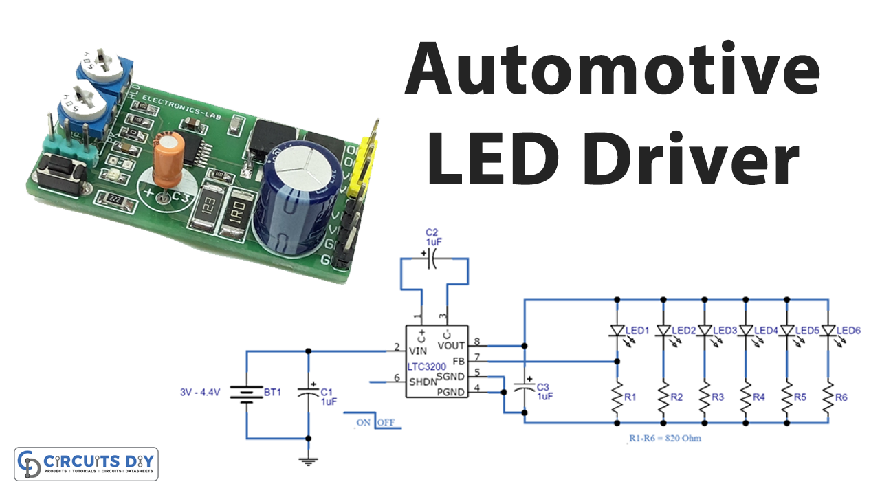
LED is a largely used electronic component or element. However, before, they were only employed as indicators or in display applications. But, with the advancement of white LED, they are now employed in many lighting applications. For example, they are now adopted as street lights, etc. LEDs are now found everywhere. Thus, some technologies help these LEDs to emit white light or radiation. And, some circuits drive these To rectify or convert higher voltage alternating current to low voltage direct current for LEDs, LEDs require the driver circuit. We use ICs for this purpose and these ICs do not require any external components and can drive an LED of 250mA. So, we have decided that in this tutorial, we are going to create an “Automotive LED Driver Circuit”
Hardware Required
| S.no | Component | Value | Qty |
|---|---|---|---|
| 1. | IC | LTC3200 | 1 |
| 2. | Battery | 3v-4.4v | 1 |
| 3. | LED | – | 6 |
| 4. | Electrolysis Capacitor | 1μF | 3 |
| 5. | Resistor | 82Ω | 6 |
Circuit Diagram

Working Explanation
This Automotive LED Driver Circuit immediately turns on the LEDs when there is no AC power supply. The normally open (N/O) terminal of the relay is wired with a DC supply while the normally close (N/C)terminal of the relay is connected with an LED array. We connected the coil terminals of the Relay to the DC supply. During the input AC power supply presence common terminal of the relay is brought to normally open and therefore the battery gets DC Supply for charging. When there is no AC input Relay coil doesn’t get DC supply and in that case, it is attached to the common terminal with normally close, now the battery supply flows through the LED array and the LED glows.
Application and Uses
- Street lights.
- Indoor lighting systems.
- Emergency lights.
- Display circuits, etc

