Introduction
Assume you had an exam the other day and your neighborhood was experiencing a load-shedding issue. It’s now late at night, and you’ll need a light to study. What would you do in this situation? As a result, the emergency light is the sole option in the circumstances. When the power is off, emergency lights are used, and the light immediately turns on. They are used as emergency illumination in homes, workplaces, and study rooms to avoid sudden power outages. As a result, we’ve opted to create an “Automatic Rechargeable LED emergency light circuit” in this tutorial. Automatic Emergency lighting is a simple setup circuit that may be completed quickly. The Emergency Light circuit’s components are readily available and affordable. When it comes to energy saving, it’s good to use that.

Hardware Components
The following components are required to make LED Emergency Light Circuit
| S.no | Component | Value | Qty |
|---|---|---|---|
| 1. | Transformer | – | 1 |
| 2. | Resistor | 1K, 10K | 3, 1 |
| 3. | Diode | 1N4007 | 6 |
| 4. | Regulator IC | 7808 | 1 |
| 5. | LDR | – | 1 |
| 6. | NPN Transistor | BC548 | 1 |
| 7. | MOSFET | IRF450 | 1 |
| 8. | LED | – | 1 |
| 9. | White LED Array | – | 1 |
| 10. | Switch | – | 1 |
| 11. | Electrolyte Capacitor | 470uF | 1 |
| 12. | Ceramic Capacitor | 0.1uF | 1 |
| 13. | Potentiometer | 10K | 1 |
| 14. | Battery | 6v | 1 |
7808 Pinout

For a detailed description of pinout, dimension features, and specifications download the datasheet of 7808
LED Emergency Light Circuit
Working Explanation
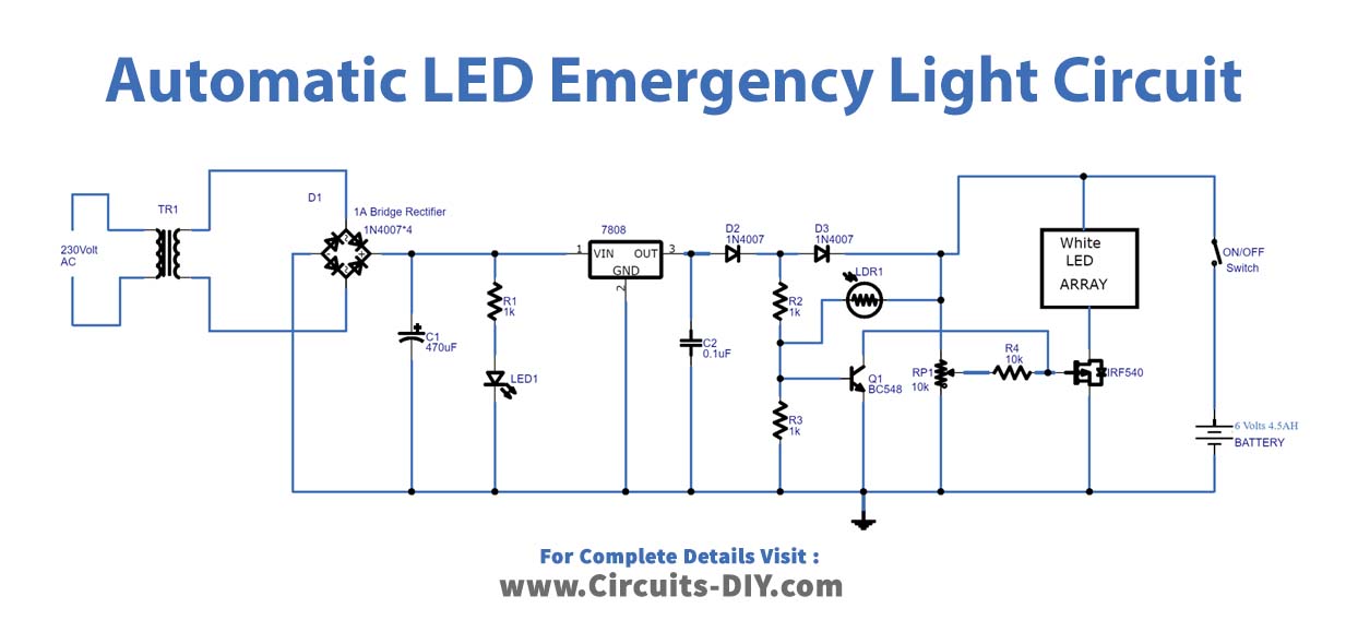
A step-down transformer is utilized in the Automatic LED emergency light circuit to convert the AC 220V input power source to 12V. We then utilized the diode bridge to convert the transformer’s 12v AC output to 12v DC output. After converting this 12v to DC, the voltage has ripples in it, which are reduced by employing a 470uf of the capacitor. The LED connected after the capacitor is used to show how much current is going through the circuit, while the equivalent resistance of 1K protects the tiny LED from the high voltage of 12 volts. After that, The 7808 voltage regulator regulates 12 volts to 9 volts.
There is an LDR in the circuit, which detects light we may adjust The LDR sensing level using the potentiometer VR1. When there is light, the LDR permits current to flow through it to the base of the Q1 transistor, causing the Q1 transistor to switch on and link the MOSFET gate terminal to the ground, disconnecting the LED array from the DC bias ground supply.
When the light goes off, the LDR prevents current flow, ensuring that the Q1 transistor’s base receives the lowest voltage possible, preventing the transistor from turning on. As a result, the Q1 transistor remains turned off since no current flows between the collector and the emitter, which is emitter open. Because no voltage is applied to the MOSFET’s gate terminal, current flows between the drain and source terminals, causing the LED to glow. A battery is connected across the bias, providing power to the circuit in the event of a power loss.
Application and Uses
- One can use it in night lamps, street lights, etc.
- The circuit is useful where there are load-shedding issues.
- Also, can be employed to avoid sudden power failures at workplaces.





Hi, the mobile signal booster. What is it’s transmission radius. In other words how far can the phone be and still get the boosted signal?
Thanks for the great job.