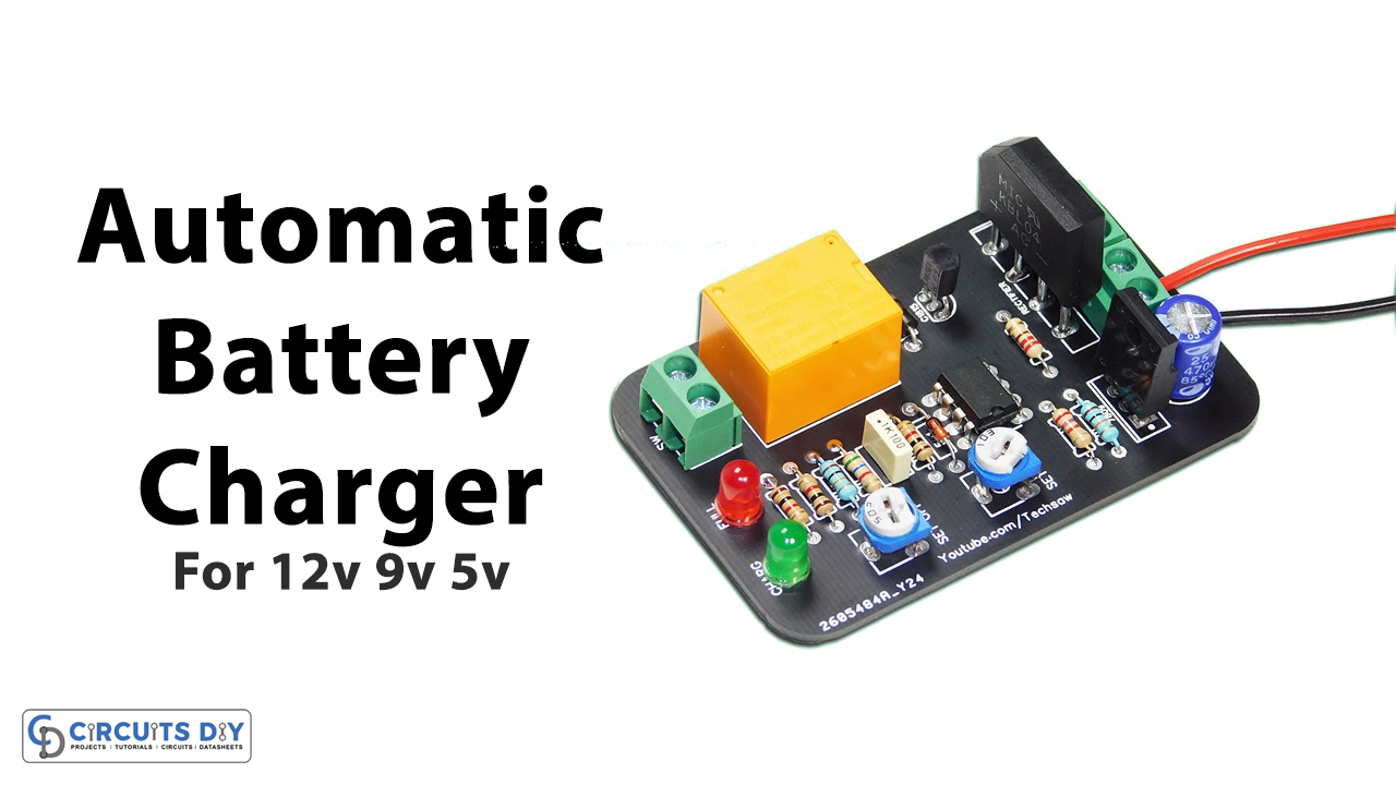
In this tutorial, we are making an easy project of 12V, 9V, and 6V Automatic battery chargers. This circuit can charge batteries of three different voltages. This voltage can be set by two different set points in the circuit i.e., VR1 and VR2. This is a simple and inexpensive circuit of an automatic battery charger, it automatically starts and stops charging the battery on preset voltages.
It also saves your battery from deep or complete discharge. Rechargeable batteries are expensive and they have a tendency of getting discharged when not charged when their battery levels fall below 50%. This results in short battery life. But this circuit makes sure to save your batteries from these issues.
Hardware Components
The following components are required to make Automatic Battery Charger Circuit
| S.no | Component | Value | Qty |
|---|---|---|---|
| 1. | Transformer | 230V/12V 1A | 1 |
| 2. | Diode | 1N4007, 1N4148 | 4, 2 |
| 3. | Electrolyte Capacitor | 1000µF/50V | 1 |
| 4. | Battery | 12V | 1 |
| 5. | Resistor | 1KΩ, 480Ω | 8, 2 |
| 6. | Transistor | 2N4401 | 4 |
| 7. | LED | 1N4148 | 2 |
| 8 | Zener diode | 9.1V, 6.2V | 1, 1 |
| 9. | Relay | 12V | 1 |
| 10. | Switch | – | 1 |
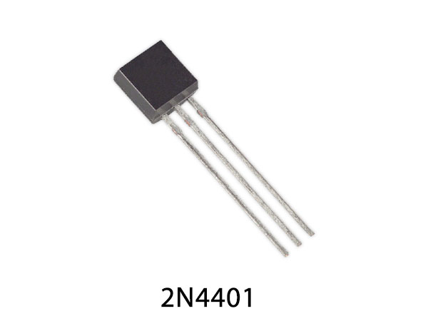
2N4401 Pinout
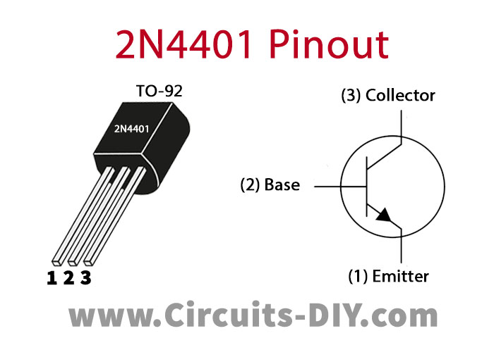
For a detailed description of pinout, dimension features, and specifications download the datasheet of 2N4401
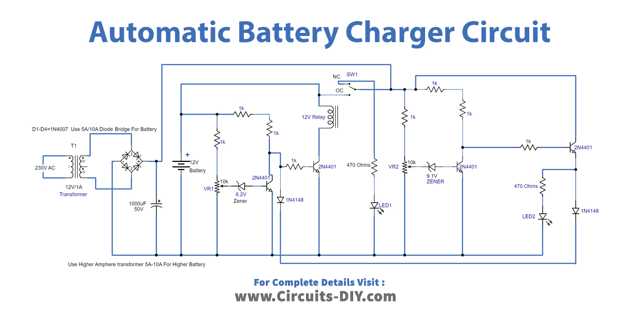
Automatic Battery Charger Circuit
Working Explanation
The first part of the circuit is working as a battery charger, the other part is responsible for starting and stopping the charging of the battery on desired voltages. We are using two variable resistors of 10K to adjust and set voltages according to the voltage of the battery being charged.
We are using a 1A transformer so this circuit can charge 12V 10AH to 12AH SLA batteries. Use 5A to 10A transformer if you need to charge batteries with higher AH.
Circuit Adjustments
Adjust the circuit by following the steps
- When a 12V battery gets weak it shows 11.9V on DMM so set the voltage in the adjustable power supply to 11.9V the battery charging start point should be set on this voltage.
- Connect this power supply in the place of the battery and adjust the VR1 until the relay activates and the green LED turns off.
- When a 12V battery becomes fully charged it shows 14.4V on DMM so now set this voltage on the power supply and connect with the NC of the relay.
- Adjust VR2 until the red LED goes off.
- Now your circuit will be ready to use, these settings were done for a 12V SLA battery. a 6 or 9V SLA battery’s circuit can be adjusted with the same procedure you just have to set the voltage levels accordingly and change Zener diodes as well.


