What is an Auto Shut Off Overvoltage Protection Circuit?
An Auto shut-off overvoltage protection circuit protects any circuit from an unstable power source, whose voltage is rising quickly by cutting off or isolating the circuit from the output of the power source. It is a common protection scheme used to protect & isolate any expensive piece of equipment from its input supply source in case of an untimely voltage spike & is also used in many consumer electronics such as modern mixers, juicers & clothing Irons, etc. So, in today’s tutorial, we are going to design a simple Auto Shut Off Overvoltage Protection Circuit using a 5V SPDT Relay.
The heart of this circuit is a 5V SPDT relay. The Relay consists of a coil, 1 common terminal, 1 normally closed terminal, and one normally open terminal. When the coil of the relay is at rest (not energized), the common terminal and the normally closed terminal have continuity. When the coil is energized, the common terminal and the normally open terminal have continuity. This relay’s coil is rated up to 5V and the contact is rated up to 30A.
JLCPCB is the foremost PCB prototype & manufacturing company in china, providing us with the best service we have ever experienced regarding (Quality, Price Service & Time).
Hardware Components
The following components are required to make Auto Shut Off Overvoltage Protection Circuit
| S.no | Component | Value | Qty |
|---|---|---|---|
| 1. | Relays | 5V, SPDT | 1 |
| 2. | High-power SMD LED | 10W/9V | 1 |
| 3. | Multimeter (optional) | – | 1 |
| 4. | Resistors | 220Ohm, 330Ohm | 2 |
| 5. | Soldering Iron | 45W – 65W | 1 |
| 6. | Soldering Wire with flux | – | 1 |
| 7. | LED | 5mm, 3.5V | 1 |
| 8. | Variable Power Supply | DC, 12V | 1 |
| 9. | Alligator Clips | – | 6 |
| 10. | Jumper wires | – | As per need |
5V Relay Pinout

Useful Steps
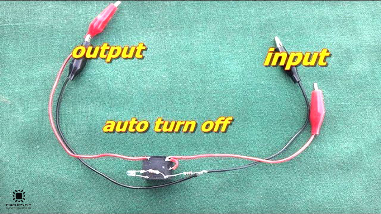
1) Solder an alligator clip with the coil terminal of the relay. After that, short the same coil terminal with the COM terminal of the relay.

2) Solder a 220 Ohm resistor with the other coil terminal. After that, solder an alligator clip with the 220Ohm resistor.

3) Solder a 330Ohm resistor with the -ve terminal of the LED. After that, solder the +ve terminal of the LED with the NO terminal of the relay & solder the 330 Ohm resistor with the 220Ohm resistor – coil junction.

4) Solder an alligator clip with the NC terminal of the relay. After that, solder another alligator clip with the 220 Ohm resistor.

5) Connect the input alligator clips with a 12V Variable DC supply & test the circuit. The relay will cut off the supply to the output LED as soon as the voltage rises above 9.5V.


Working Explanation
The working of this circuit is as follows. On powering up the DC variable supply the coils of the 5V SPDT relay energizes & make the circuit through the NC terminal of the relay. The 10W SMD LED starts to glow slowly, drawing an agreeable amount of current through the SPDT relay.
On increasing the voltage level of the 12V DC variable power supply the current draw of the 10W LED increases. On crossing the current threshold of the SPDT relay, (due to the continuously increasing voltage) the relay immediately trips & restores the switch in the NO (OFF) state, thus cutting off & isolating the 10W LED from the 12V DC power supply.
Applications
- Usually used in many consumer electronic appliances to protect them from highly unstable voltage spikes.


