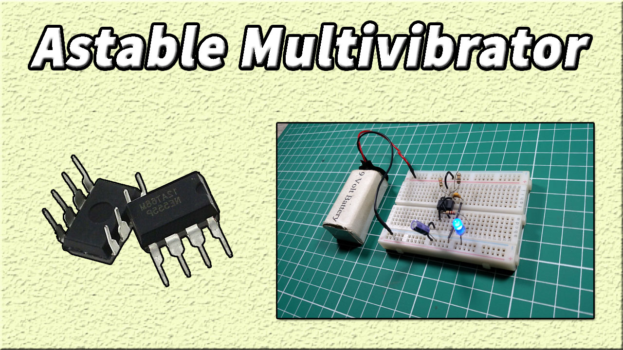
In this tutorial, we will show you how to make an Astable Multivibrator circuit using 555 Timer IC. The astable mode is also called free-running or self-triggering mode. We can operate 555 timer IC in three different modes, but here we will operate it in astable mode only. In astable mode, the output has no fixed state, and it repeatedly switches from one state to another without the application of an external trigger.

Hardware Components
The following components are required to make Astable Multivibrator Circuit
| S.NO | Component | Value | Qty |
|---|---|---|---|
| 1. | Breadboard | – | 1 |
| 2. | Connecting Wires | – | 1 |
| 3. | Battery | 9v | 1 |
| 4. | IC | NE555 Timer | 1 |
| 5. | Ceramic Capacitor | 0.01uF | 1 |
| 6. | Electrolytic Capacitor | 10uF | 1 |
| 7. | Resistor | 1K, 100K, 220 ohm | 1, 1, 1 |
| 8. | LED | 5mm | 1 |
555 IC Pinout

For a detailed description of pinout, dimension features, and specifications download the datasheet of 555 Timer
Circuit Diagram
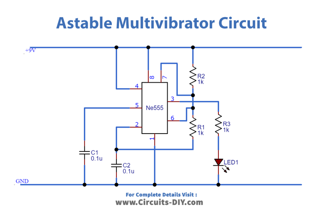
Working Explanation
In this circuit, we are operating 555 timers in an astable mode which works like a simple oscillator circuit that generates continuous pulses. We have connected the LED to Pin 3 of the IC, which is the output pin. LED will switch On and Off continuously and we can change the frequency of the circuit by changing the values of R1, R2, and C1.
Pins 2 and 6 of the 555 timers are connected together so that there is no need for an external trigger pulse and It will self-trigger and act as a free-running multivibrator. Pin 5 is connected to the ground using a capacitor, in order to filter out external noise from the terminal. Pin 4 is the external reset pin. If we apply low on this pin it will reset the timer, hence we have connected it to VCC.
Connection
- Connect Pin 4 & 8 of 555 To VCC.
- Use a jumper wire to connect Pin 6 & 2 together.
- Connect Pin 1 to GND.
- Connect 10uF Capacitor at Pin 2 and connect 0.01uF Capacitor to Pin 5.
- Use 100k Ω Resistor to connect Pin 6 to Pin 7.
- Use 1k Ω Resistor to connect Pin 7 to VCC.
- Add LED with 220 Ω resistor at Pin 3.
Application
- It is used in radio gears to transmit and receive radio signals.
- It is used as a timing oscillator or clock of a computer system.