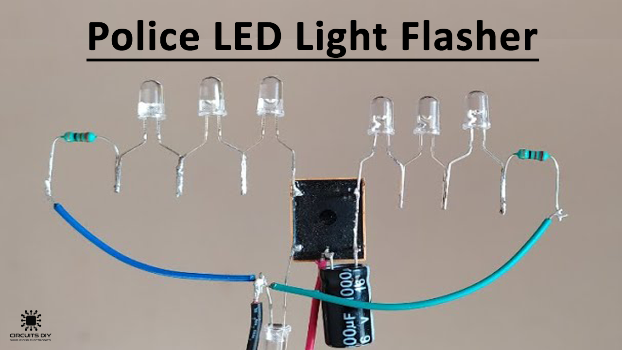
Police LED light flasher is a simple project that mimics the flashing pattern of siren lights installed on any law enforcement vehicle. It is a simple project that most electronics enthusiasts build first as it is inexpensive & relatively easy to build. So in this project, we are going to build a simple Police LED light Flasher Circuit Using 12V SPDT Relay.
The heart of this circuit is a 12V SPDT relay. The Relay consists of a coil, 1 common terminal, 1 normally closed terminal, and one normally open terminal. When the coil of the relay is at rest (not energized), the common terminal and the normally closed terminal have continuity. When the coil is energized, the common terminal and the normally open terminal have continuity. This relay’s coil is rated up to 12V and the contact is rated up to 30A.
JLCPCB is the foremost PCB prototype & manufacturing company in china, providing us with the best service we have ever experienced regarding (Quality, Price Service & Time).
Hardware Components
The following components are required to make LED Flasher Circuit
| S.no | Component | Value | Qty |
|---|---|---|---|
| 1. | Relay | 12V/5V/SPDT | 1 |
| 2. | LEDs | red/blue/5mm | 6 |
| 3. | RGB LED | 5mm | 1 |
| 4. | Capacitor | 16V/1000uF | 1 |
| 5. | Resistor | 22 Ohm | 2 |
| 6. | Soldering iron | 45W – 60W | 1 |
| 7. | Soldering wire with flux | – | 1 |
| 8. | DC Power Supply | 12V | 1 |
| 9. | Connecting wire | – | As per need |
Useful Steps
The following are the steps on ‘How to make Police LED light Flasher Circuit.
1) Solder the red & the blue LEDs together individually into 2 pairs, after that solder a 22 Ohm resistor with each pair of LEDs.

2) Solder the blue led pair across the NC (normally close) & coil 2 terminal of the SPDT relay, After solder a connecting wire to the COM terminal of the SPDT relay.
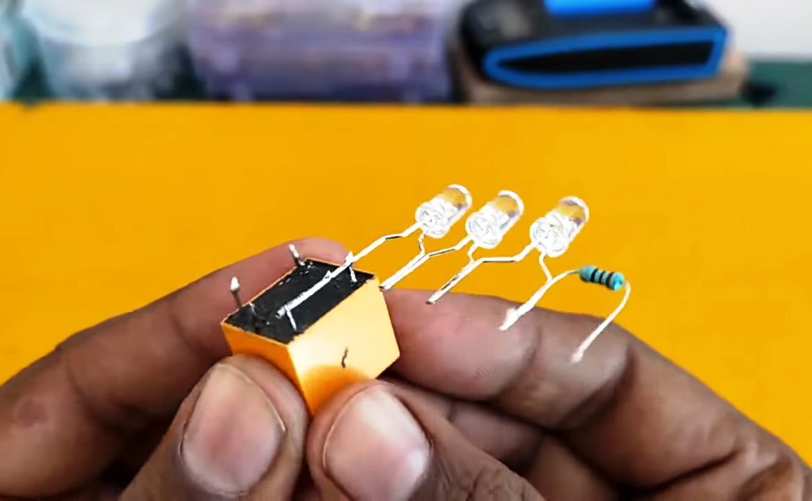
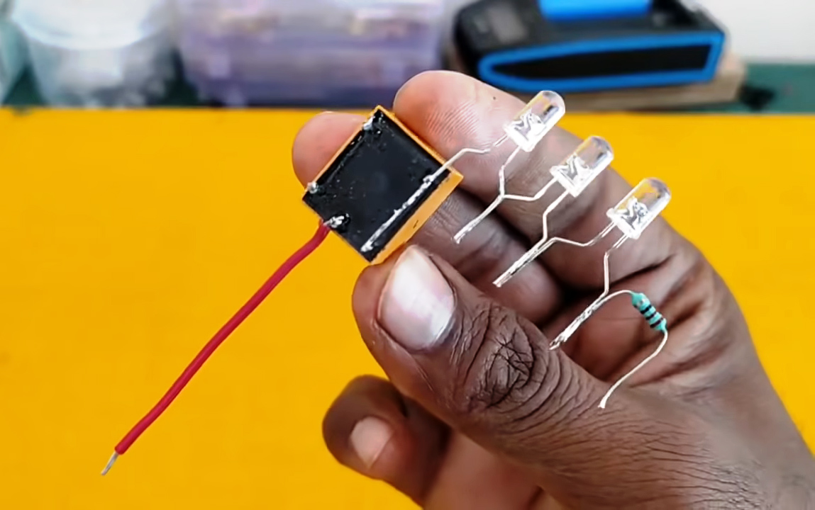
3) Solder a 1000uF capacitor across the COM port & the coil 2 terminal.
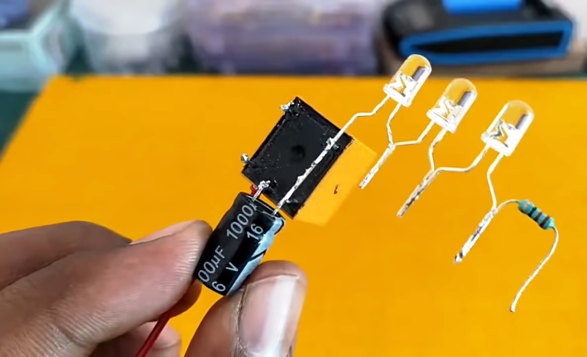
4) Connect the red led pair with the 22 Ohm resistor to the NO terminal of the SPDT relay.

5) Connect the -ve terminal RGB led between coil 1 terminal of the SPDT relay & the 22 Ohms resistors of both (red & blue led) pairs.
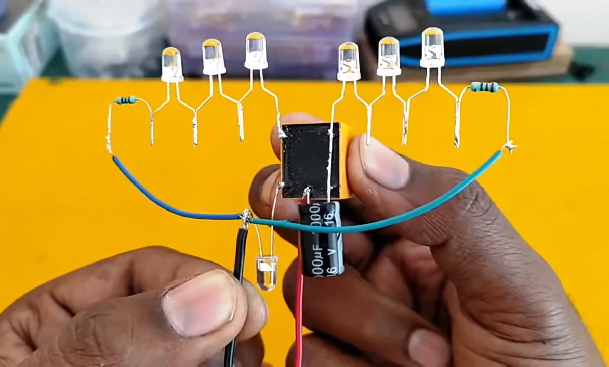
6) Connect a power supply to the COM & negative terminal of the circuit & then test it.
Working Explanation
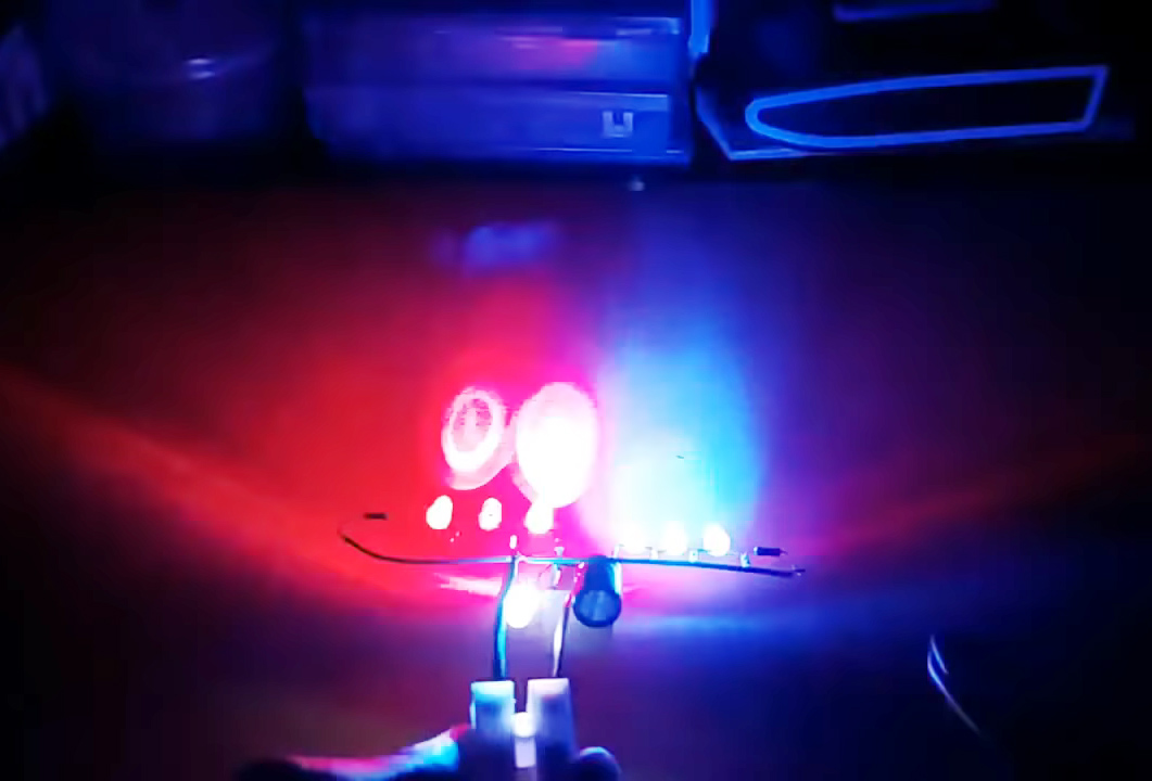
The working of the circuit is pretty simple. On powering the circuit, the capacitor C1 charges. When the voltage across the capacitor is sufficient, the relay switches ON and the blue LED pair connected via the normally open contact of the relay glows.
The relay remains energized until the capacitor discharges and then the lamp extinguishes. The charging and discharging cycle of the capacitor gives a flashing effect to the lamp. While the red LED pair flashes as per the operation of the relay.
Applications
- Commonly used in police vehicles to alert the general public.

