What is an Electronic Fuse Circuit?
An Electronic fuse is a safety device that is designed around a conductive strip, it is intended to break or melt in the event of any excessive current flowing through the device. A fuse is always connected in series with the device that is intended to be protected, So that when the fuse blows, the flow of current to the device immediately stops. The thin piece of wire within the fuse is normally covered by a safety sheath, so to act against the hazards of any undesirable arc blast if the wire burns open with violent force, which sometimes happens in case of severe overcurrents. So, in today’s tutorial, we are going to go over a step-by-step procedure on how to make an Electronic fuse circuit using a small no. of components.
JLCPCB is the foremost PCB prototype & manufacturing company in china, providing us with the best service we have ever experienced regarding (Quality, Price Service & Time).
Hardware Component
The following components are required to make Electronic Fuse Circuit
| S.no | Component | Value | Qty |
|---|---|---|---|
| 1 | Fuse Box | 1A | 1 |
| 2 | LED | 5mm, 3.5V | 2 |
| 3 | Terminal Block Connectors | – | 2 |
| 4 | Resistors | 47K | 2 |
| 5 | Soldering Iron | 45W – 65W | 1 |
| 6 | Soldering Wire with flux | – | 1 |
| 7 | AC Bulb with Base | 220V | 1 |
| 8 | AC Wall outlet | 220V | 1 |
| 9 | Veroboard | – | 1 |
| 10 | Jumper Wires | – | As per need |
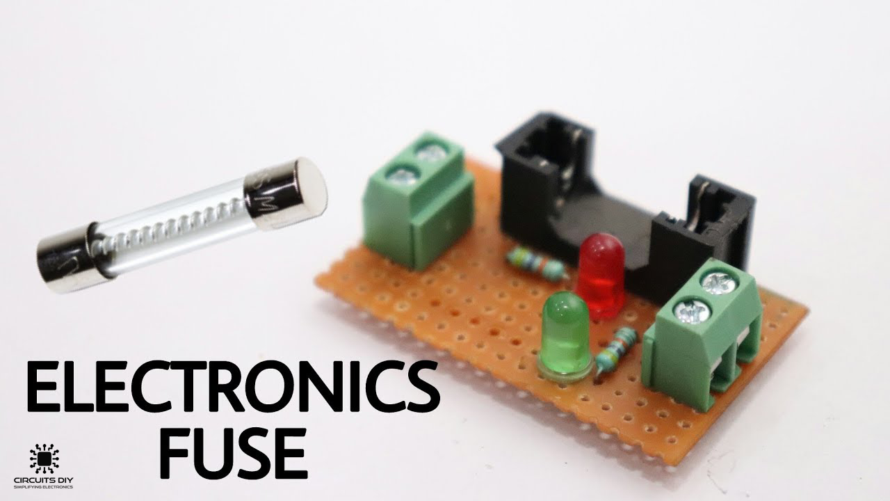
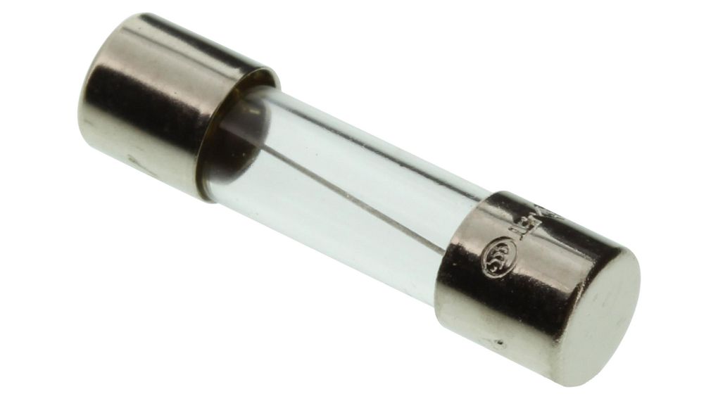
Electronic Fuse
Electronic Fuse Circuit
Useful Steps
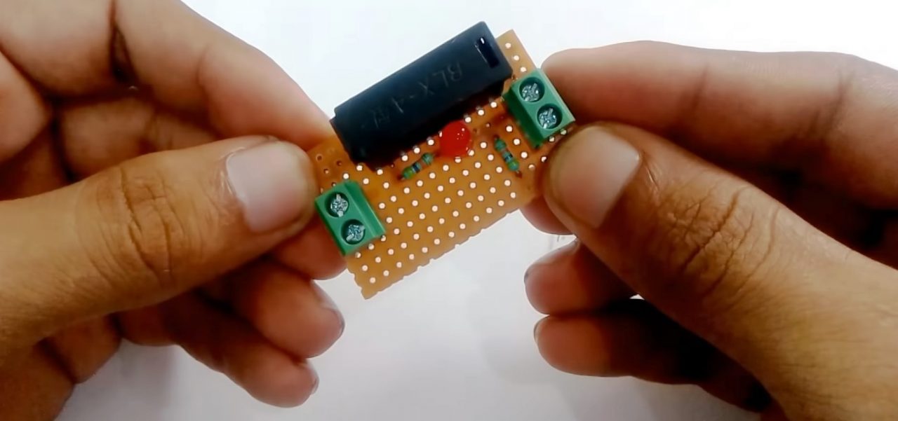
1) Solder the fuse box on the Veroboard. After that, solder the After solder the I/O terminal block connectors on the Veroboard.

2) Solder a 47K resistance on the first terminal of the fuse. After that, Solder the red LEDs +ve terminal with the 47K resistor & the -ve terminal with the second terminal of the fuse.
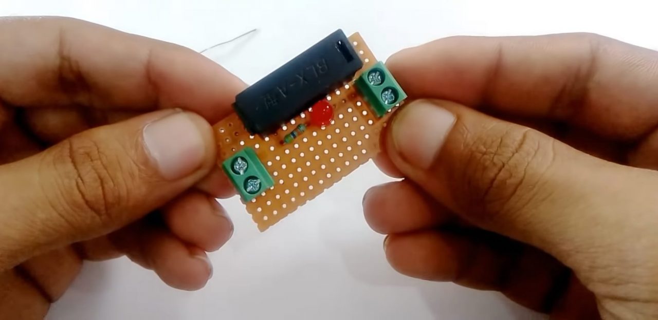
3) Solder a 47K resistor on the second terminal of the fuse.
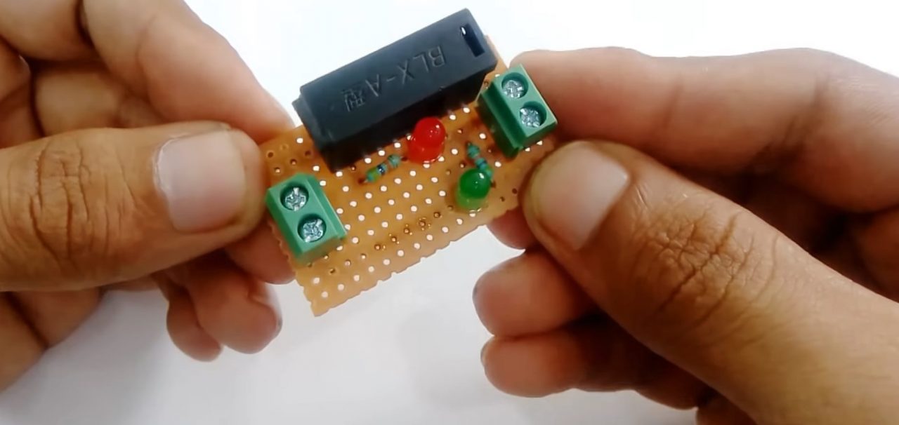
4) Solder the +ve terminal of the green LED with 47K resistor & the -ve terminal to the GND of the circuit.
5) Connect the load (220V AC bulb) to the output terminal block connector. Now power up & test the circuit.
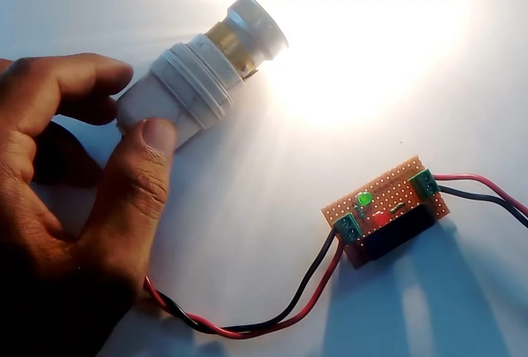
Working Explanation
The working of this circuit is very simple. During the normal operation of the circuit, the fuse will behave similarly to a piece of wire. In the case of this circuit, when any excessive current passes through the fuse, it starts to heat up. In case of an immense instantaneous current flow, the fuse wire will instantly blow violently, protecting the external component or circuit to which it is attached in series.
Here we are using two LEDs (red & green) to indicate the status of the fuse. Green LED indicates that the circuit is operational & the fuse is intact. While the red LED indicates that the circuit is inactive & the fuse is blown.
Applications
- Fuses are usually used in applications such as power chargers, AC equipment & home cabling, etc.