In this tutorial, we are making a project of a low-cost 8 LED battery monitor using LM324 IC. LM324 is an IC that contains four op-amps. Therefore we have used two ICs in this circuit to create 8 voltage levels of the battery monitored. This circuit will monitor batteries with different kinds and voltages and saves them from getting deep discharged. The rechargeable battery gets deep or fully discharged f they are not charged when its voltage level falls to 50%.
Hardware Components
The following components are required to make LED Battery Monitor Circuit
| S.no | Component | Value | Quantity |
|---|---|---|---|
| 1. | Battery | – | 1 |
| 2. | IC | LM324 | 2 |
| 3. | LED | – | 8 |
| 4. | Resistor | 10K, 680Ω | 1, 8 |
| 5. | Variable Resistor | 10KRΩ | 8 |
| 6. | Zener diode | 3V | 1 |
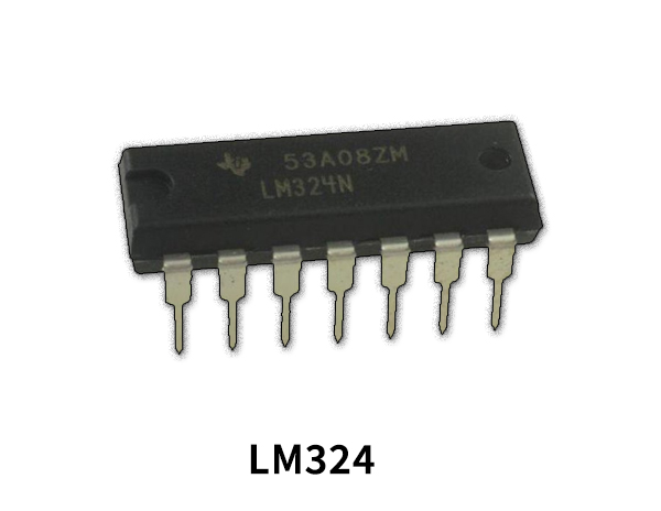
LM324 Pinout

For a detailed description of pinout, dimension features, and specifications download the datasheet of LM324
LED Battery Monitor Circuit
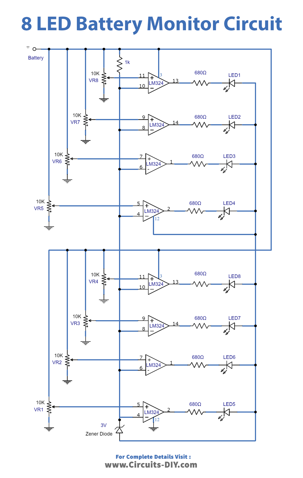
Working Explanation
All the op-amps are working as a comparator to detect the voltage level preset by a variable resistor of 10K. This circuit is using 8 LEDs, each of which switches off at the preset voltage levels.
Before using this circuit you need to follow these steps to tune your circuit.
- If you are using a 12V battery then take an adjustable power supply and set its output voltage to 12.6V.
- Now replace the battery with this power supply in the circuit.
- Start adjusting the variable resistor VR1 until LED1 turns off.
- Now set the voltage on the adjustable power supply to 12.5V and Adjust the VR2 slightly until LED2 turns off.
- Set the voltage to 12.4V in the power supply and adjust the VR3 until LED 3 goes off.
- Again change the voltage to 12.3V and adjust the VR4 this time until LED 4 goes off.
- Decrease the voltage to 12.2V and adjust the VR5 this time until LED5 goes off.
- Change the voltage to 12.1V and adjust the VR6 until LED 6 goes off.
- Change the voltage to 12V and adjust the VR7 this time until LED7 goes off.
- Now for the last level set the voltage to 11.9V and adjust VR8 until LED8 goes off.
- After these adjustments do a final check by increasing the voltage of the adjustable power supply to 12.6V and slightly down to 11.9V. At this point, all the LEDs will go off one by one on their preset voltages.
The same procedure can be repeated for other batteries and the circuit should be adjusted according to battery voltage.
Applications and Uses
This circuit can be used with any battery having voltages from 4.5V to 24V.