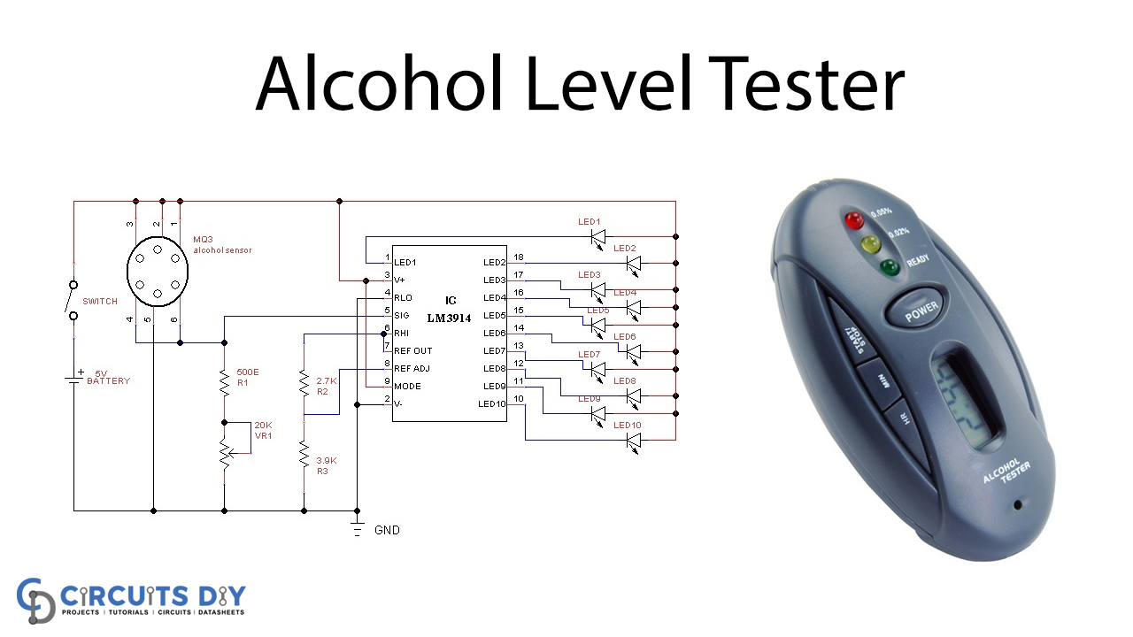
In this tutorial, we are developing a project of an Alcohol level tester bar graph. This circuit is very helpful for testing whether or not a driver is drunk. The circuit is easy to use, low-priced, and shows different levels of alcohol intake using LEDs. The MQ3 alcohol sensor was used to sense the alcohol intensity on this LM3914 bar-graph decoder IC circuit, and the output signal was applied to the input pin LM3914 bar graph decoder.
Hardware Components
The required hardware components for making an Alcohol level tester bar graph are as under:
| S.no | Component | Value | Qty |
|---|---|---|---|
| 1. | IC | LM3914 | 1 |
| 2. | Alcohol Sensor | MQ3 | 1 |
| 3. | Variable Resistor | 20KΩ | 1 |
| 4. | LED different color | – | 10 |
| 5. | Connecting Wires | – | – |
| 6. | Resistor | 2.7kΩ, 3.9kΩ, 500Ω | 1, 1, 1 |
Circuit Diagram
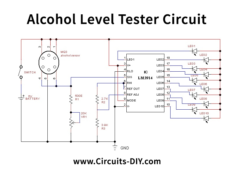
Working Explanation
The alcohol sensor MQ3 was used for the sensation of the alcohol intensity on this LM3914 bar-graph decoder IC circuit and the output signal was fed to the input pin LM3914 bar graph decoder. This circuit works on a +5V power supply; the sensitivity level can be varied by a variable resistor, while the output is indicated by the different color LED.
This circuit works on a power supply of +5V; the sensitivity levels can vary by the variable resistor VR1 as the output is indicated through different color LEDs.
Application and Uses
The MQ3 alcohol sensor is used to detect alcohol intensity, and the output signal is fed into the LM3914 bar graph decoder input pin, used in this circuit LM3914 Bar graph decoder IC for drive output.


