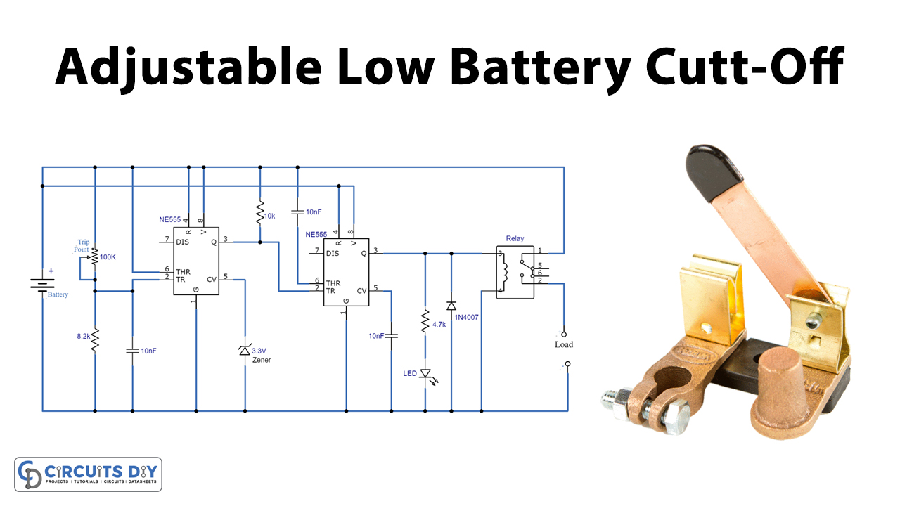
In this circuit, we are making an Adjustable Low Battery Cutoff For All Rechargeable Batteries. Battery charging always has an issue of them getting deep discharged or being fully discharged that completely damages them or shortens their life. Rechargeable batteries are very expensive and this issue can waste your money. To solve this problem we came up with this circuit.
This circuit will disconnect the battery from the load as soon as it reaches its threshold voltage. In this way, your battery will be saved from getting completely discharged and provides long battery life.

Hardware Components
The following components are required to make an Adjustable Low Battery Cutoff Circuit
| S.no | Component | Value | Quantity |
|---|---|---|---|
| 1. | IC | NE555 Timer | 2 |
| 2. | Potentiometer | 100K | 1 |
| 3. | Resistor | 8.2K, 4.7K, 10K | 1, 1, 1 |
| 4. | Capacitor | 10nF | 3 |
| 5. | Diode | 1N4007 | 1 |
| 6. | Relay | – | 1 |
| 7. | Zener diode | 3.3V | 1 |
| 8. | LED | – | 1 |
| 9. | Battery | – | 1 |
NE555 IC Pinout

For a detailed description of pinout, dimension features, and specifications download the datasheet of 555 Timer
Adjustable Low Battery Cutoff Circuit
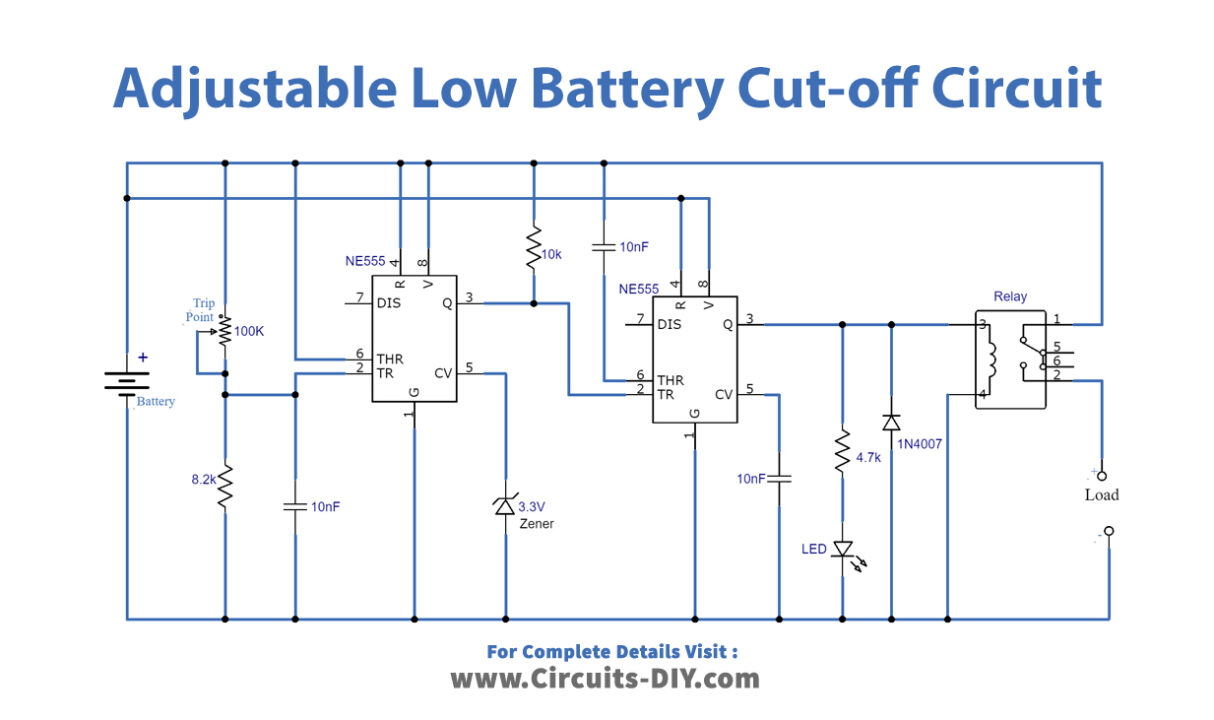
Circuit Setup
- After completing this circuit you will need to do some calibration before using it. Disconnect the battery from the circuit and connect an adjustable power supply instead.
- Set this power supply at the voltage on which you want to disconnect the battery from the load.
- If you are using a 12V battery then set 11.9V in an adjustable power supply and adjust the 100K pot/trip point until the LED turns off.
- For a 6V battery set the voltage in an adjustable power supply to 5.9V and again adjust the trip point until the LED turns off.
- When you are done with these adjustments remove the adjustable power supply and reconnect the battery. Now your circuit is ready to use.
Working Explanation
We are using two 555 timer ICs in this circuit. This circuit monitors a battery and disconnects it with the load when it will reach the threshold voltage. This threshold voltage is adjustable and is set by a 100K potentiometer. A LED is used in the circuit which turns on when the battery is connected with the load and turns off automatically when the battery is disconnected. A relay is connected at the output of this circuit, you can connect the load there.
This circuit can be used with batteries of all voltages and types like lithium-ion, lead-acid, etc. It can also be used with any voltage battery made with a separate 1.2V or 3,6V rechargeable cell.


