Introduction
Have you ever wondered how much current your various electrical appliances need? Varying devices demand different amounts of electricity, so if the incorrect amount is supplied to them, it might lead to severe situations. For example, when a large quantity of electricity is sent to some devices, they get damaged because they are so sensitive. Therefore, measuring current is vital to prevent situations like these and to keep track of the current needed or consumed in a particular application. So, in this article, we will interface the ACS712 Current Sensor with Arduino.
Electrical appliances exist in a variety of sizes and designs, from your refrigerator to your phone, laptop, or computer. Different devices require different amounts of electricity to operate properly—and, more crucially, to avoid being harmed by excessive power. Due to this, current sensing is considered a crucial element of the power supply.
What is ACS712 Current Sensor?
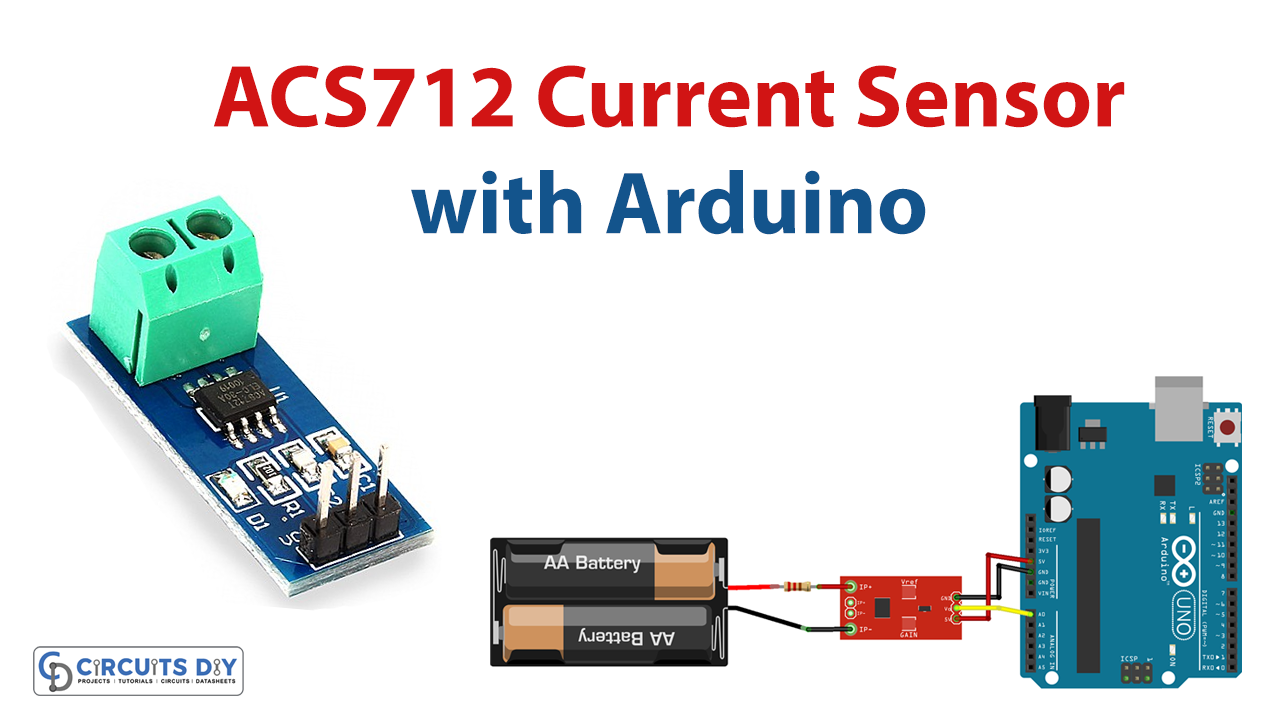
The ACS712 is a completely integrated, Hall effect-based linear current sensor featuring 2.1kVRMS voltage isolation and an integrated low-resistance current conductor. Aside from the technical terms, it is simply described as a current sensor that employs a conductor to compute and analyze the amount of current supplied.

Hardware Components
You will require the following hardware for ACS712 Current Sensor.
| S.no | Component | Value | Qty |
|---|---|---|---|
| 1. | Arduino UNO | – | 1 |
| 2. | Current Sensor | ACS712 | 1 |
| 3. | Resistor | 1Ω 8watt | 1 |
| 4. | Breadboard | – | 1 |
| 5. | Jumper Wires | – | 1 |
Steps Making Current Sensor
To interface ACS712 Current Sensor with Arduino, you require very few components. A list is given above. Once you have them all; follow the given below steps:
Schematic
Make connections according to the circuit diagram given below.

Wiring / Connections
| Arduino | ACS712 Current Sensor | Battery |
|---|---|---|
| 5V | VCC | |
| GND | GND | |
| A0 | OUT | |
| IP+ | +Ve | |
| IP- | -Ve |
Installing Arduino IDE
First, you need to install Arduino IDE Software from its official website Arduino. Here is a simple step-by-step guide on “How to install Arduino IDE“.
Code
Now copy the following code and upload it to Arduino IDE Software.
void setup() {
  Serial.begin(9600); //Start Serial Monitor to display current read value on Serial monitor
}

void loop() {
unsigned int x=0;
float AcsValue=0.0,Samples=0.0,AvgAcs=0.0,AcsValueF=0.0;

  for (int x = 0; x < 150; x++){ //Get 150 samples
  AcsValue = analogRead(A0);     //Read current sensor values
  Samples = Samples + AcsValue;  //Add samples together
  delay (3); // let ADC settle before next sample 3ms
}
AvgAcs=Samples/150.0;//Taking Average of Samples

//((AvgAcs * (5.0 / 1024.0)) is converitng the read voltage in 0-5 volts
//2.5 is offset(I assumed that arduino is working on 5v so the viout at no current comes
out to be 2.5, which is the out offset. If your arduino is working on different voltage than
//you must change the offset according to the input voltage)
//0.066v(66mV) is rise in output voltage when 1A current flows at input
AcsValueF = (2.5 - (AvgAcs * (5.0 / 1024.0)) )/0.066;

Serial.print(AcsValueF);//Print the read current on Serial monitor
delay(50);
}
Let’s Test It
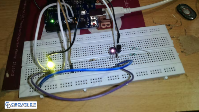
It’s now time to test the circuit. So, after making connections and uploading the code, provide a little current on the input side of the sensor; open the serial monitor, and observe the readings.
Working Explanation
- First, in the void setup, we initialize the serial monitor.
- In the void loop, we first define the unsigned integer variable named x to store values from zero to positive numbers. Initially, we store zero in it. Next, we define four float variables that would store numeric values with floating points, we named them AcsValue, Samples, AvgAcs, and AcsValueF.
- We then create the for loop to get 150 samples and give the function to read sensor values coming from Arduino analog pin A0, we store this value in AcsValue. To get the Samples value we add the value of the previous sample to this AcsValue. We then give a little delay to allow the ADC to settle before getting the next sample.
- Then to take the average of Sample values we divide them by 150 ( as we took 150 samples earlier) and stored that value in AvgAcs.
- Then to read the value from 0 to 5V we provide the formula and stored it in AcsValueF.
- Next, we simply print that AcsValueF on the serial monitor.
- In the end, we give a little delay to get the next readings.
Applications
- Peak detection circuits
- Rectification application for Analog to Digital converters
- Overcurrent fault protection
- Automobile applications; etc
Conclusion.
We hope you have found this ACS712 Current Sensor Circuit very useful. If you feel any difficulty in making it feel free to ask anything in the comment section.