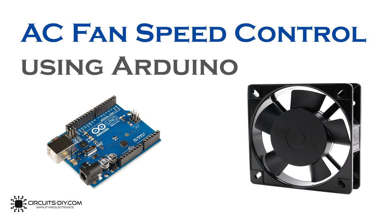
In this tutorial, we are going to make a project of AC Fan speed control using Arduino and TRIAC. Turning any electronic appliance on and off is easy by various automation projects in which control mechanism technique is used but many times we are required to control the AC power partially like controlling the intensity of light or the speed of a fan. For that, we use the PWM technique. PWM is known as pulse width modulation, in this technique, the average voltage sent to the load is controlled by turning the switch between the input supply and load on & off at a fast rate, that is how it generates variable width pulses which can help in controlling the speed of a fan. These PWM signals are generated by an Arduino.
Hardware Required
| S.no | Component | Value | Qty |
|---|---|---|---|
| 1. | Stepdown Transformer | 0-9V, 500mA | 1 |
| 2. | Zero crossing detector (optocoupler) | 4N25 | 1 |
| 3. | Arduino | Uno | 1 |
| 4. | Potentiometer | 10KΩ | 1 |
| 5. | Opto-coupler | MOC3021 | 1 |
| 6. | TRIAC | BT136 | 1 |
| 7. | Axial AC fan | 230 VAC | 1 |
| 8. | Resistor | 330Ω, 10KΩ, 39Ω, 1KΩ | 1, 1, 1, 1 |
| 9. | Capacitor | 10nF | 1 |
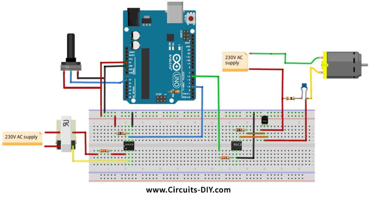
Circuit Diagram
Working Explanation
The first step in the working of this circuit is to detect the zero-crossing point, it is the point on the voltage curve where the voltage changes the direction. A 220V mains voltage is stepped down to 9V using a step-down transformer and then it is sent to a 4N25 Optocoupler. This optocoupler has a built-in LED and an output transistor that de-actives when the AC wave goes close to the zero-crossing point and they both are activated when the signal increases to the peak point.
Using this pulse the zero-crossing point is detected by the Arduino. Then we have to control the time period for which the power will on and off. It is done by a BT136 Triac. The speed of the fan is adjusted or varied through a 10K potentiometer. The Arduino will take the input from the potentiometer and generates a PWM signal which is fed into the TRIAC and optocoupler circuit that will result in operating the AC fan at the desired speed. The PWM signal will decide the amount of voltage output to the AC motor that controls the speed of it.
Arduino Code
int TRIAC = 6;
int speed_val=0;
void setup()
{
  pinMode(TRIAC, OUTPUT);
  attachInterrupt(digitalPinToInterrupt(3), zero_crossing, CHANGE);
}
void zero_crossing()
{
  int chop_time = (200*speed_val);
  delayMicroseconds(chop_time);
  digitalWrite(TRIAC, HIGH);
  delayMicroseconds(10);
  digitalWrite(TRIAC, LOW);
}
void loop()
{
    int pot=analogRead(A0);
    int data1 = map(pot, 0, 1023,10,40);
    speed_val=data1;
}
