Don’t you love to learn about the controllers behind these electronic devices, smartphones, computers, and other electrical and electronic devices? If you have a strong interest in and passion to make electronic projects, then we are sure that you must want to read and understand the brain behind them. But, to learn a specific microcontroller, one must need to know about the microcontroller. The simplest way to understand a microcontroller is to take it as an individual brain. Just like a human brain controls the action and features of humans, the microcontroller controls the actions and features of Electronic devices and products. Hence, there are many microcontrollers available for these purposes like AVR, 8051 microcontrollers, pic microcontrollers, etc. But, here in this article, we will only discuss the whole beginner’s guide to Atmel AVR microcontrollers.

What are Atmel AVR Microcontrollers?
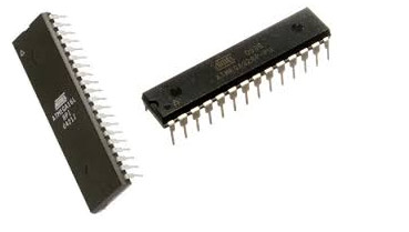
Atmel cooperation designers, Alf-Egil Bogen and Vegard Wollan created Alf-Egil Bogen and Vegard Wollan’s RISC processor, which is commonly known as an AVR. The AVR microcontrollers are a modified form of Harvard RISC architecture having separate memories for data and programs. Hence the speed of AVR microcontrollers is higher than 8051 and PIC microcontrollers. In this article we are going to discuss:
- AVR Architecture
- Features of AVR
- Classification of AVR microcontrollers.
- Atmega32 AVR microcontroller (features and pin configuration).
- Programming of AVR.
AVR Architecture
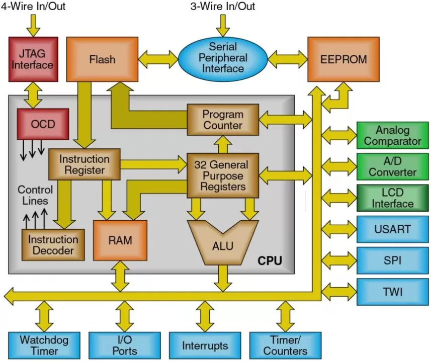
They based AVR architecture on advanced RISC ( reduced instruction set computer) architecture. The architecture incorporates CPU, Flesh program memory, SRAM, EEPROM, analog and digital input/output modules, interrupt, and timer, all we are going to examine below.
CPU:
The Central Processing Unit of the microcontroller is the same as the ordinary computer’s CPU and comprises
- ALU for the arithmetic operations
- General-Purpose Registers.
- Status Register.
- Program Counter.
- Instruction Register.
- Instruction Decoder.
- Stack Pointer.
Program Memory
The program which you write get stored in the non-volatile flash program memory. The memory has two units:
- Application Flash Section: To store the program of an AVR.
- Boot Flash Section: To perform directly when the microcontroller gets the power.
SRAM
Static random access memory is the volatile memory that is pre-designed in 8-Bit registers to apply data through the runtime when registers are doing calculations.
EEPROM
Electronically Erasable Read-Only Memory is a nonvolatile memory that is there to store device parameters and system configuration at runtime. Since it’s non-volatile so one can store programs for a long time.
Analog Input/Output Module
To communicate the data from external components, there are analog input and output modules including Analog to digital converters and comparators.
Digital Input/Output Module
To allow digital communication between the microcontroller and external components, there is a digital input and output module.
Interrupts
Interrupts allow the AVR microcontroller to monitor specific events in the background while performing. Hence respond to any occurrence if happened by pausing the particular program. Thus, interrupts synchronized this all.
Timer
Every Atmel AVR microcontroller has at least one timer used to generate specific time delays between two operations.
Watchdog
Every AVR microcontrollers have an internal timer which is known as a watchdog. Although It has very few useful features including :
- 128kHz distinct clock source.
- To reset the microcontroller and produce an interrupt.
Serial Communication
To transfer one-bit data at a time there is a method called serial communication. It uses three protocols which are described below.
USART: This synchronous and asynchronous receiver and transmitter allows serial communication between two devices. It transfers or receives the signal bit by bit regarding the clock signal.
SPI Protocol: This Serial Peripheral Interface is used to transfer the data between the microcontroller and other devices like registers, sensors, etc. This protocol has better data handling capability or capacity than the USART protocol.
12C Protocol: This protocol is used to connect low-speed devices like microcontrollers, analog-to-digital converters, etc.
Features of AVR
- The AVR microcontrollers have 16KB of Programmable Flash.
- Also, it has 512B of Programmable EEPROM
- Moreover, It contains a 16-bit Timer
- Furthermore, it has Multiple internal oscillators
- The microcontroller contains self-programmable instruction flash memory of up to about 256K
- There is also an optional boot code segment with independent lock bits for protection
- It comprises Synchronous and asynchronous serial peripherals which are known as USART and UART, respectively.
- Serial peripheral interface Bus which is commonly known as SPI is there too.
- Universal serial interface, i.e. USI is present for synchronous data transfer.
- Further, the Watchdog timer reset and produce an interrupt.
- Various power-saving sleep modes are present.
- 10-bit analog-to-digital converter, with a multiplex of up to 16 channels.
- There is also a USB controller support.
Classification of AVR microcontroller
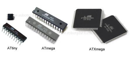
They basically classified intel AVR microcontrollers into three types.
- Tiny AVR.
- Mega AVR.
- Xmega AVR.
Tiny AVR
Basically, tiny AVRs are those having less memory and small size. Therefore, used in small applications.
Features
- They have 0.5 to 16 kB program memory.
- And, have a 6-32 pin package.
- They contain a limited peripheral set.
Examples: AtTiny13, ATtiny25, ATtiny44, ATtiny84.
Mega AVR
Mega AVRs are those having a good amount of memory. Also, it contains a higher number of peripherals. Therefore, used in moderate or complex applications. Hence, they are highly popular.
Features
- They have 4 to 512 kB program memory.
- And, have a 28-100 pin package.
- They contain an extensive peripheral set.
Examples: Atmega8, ATmega16, ATmega32, ATmega64.
X Mega AVR
Mega AVRs are those having an extensive amount of memory. Thus, used in complex applications.
Features
- They have 16 to 384 kB program memory.
- And, have 44–64–100 pin package.
- They contain an extensive peripheral set with ADCs.
Example: ATXMEGA128A1U.
Atmega32 AVR microcontroller
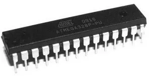
Atmega32 is a simple AVR controller. With program memory, it convinces most embedded systems. And, with various sleep modes, it can perform great on the mobile embedded system It has Input and Output pins so that you can interface with many peripherals. With so many features with each appreciating other, you can easily carry out ATMEGA32 in many control systems.
As we have discussed that because of extensive peripherals and other features, we extensively used mega AVR ICs in both complex and moderate applications. Hence it has industrial and commercial applications. In these mega ICs designers widely use the ATmega32 microcontroller IC. So, we are going to discuss its features and pin configurations.
Features of Atmega32
- These AVR microcontrollers have 328KB of in-system Programmable Flash.
- Also, it has 1024B of Programmable EEPROM.
- Moreover, It contains 3 flexible counters/Timers with compare mode.
- Furthermore, it has an internal oscillator.
- The microcontroller contains self-programmable instruction (SPI) serial port
- It comprises Synchronous peripheral, which we recognize as USART.
- Serial peripheral interface Bus which is commonly known as SPI.
- ATmega32 also has a byte-oriented two-wire Serial Interface.
- Also, it has an 8-channel, 10-bit ADC.
- Further, a programmable Watchdog timer to reset and produce interrupts. With the Watchdog timer to reset you can use it on systems with no human interference.
- It has six software-selectable power-saving modes.
- It contains internal and external interrupts.
Pin Configuration of Atmega32
There are 40 pins available including three ports having Analog-to-Digital converters, PWM pins, I/O pins, etc. We are describing all the pins below.

Port B
PB0 (Pin 14): It’s a digital input source for a timer or counter.
PB1 (PIn 15): It’s a digital PWM input timer comparison.
PB2 (Pin 16): It’s a digital PWM pin that works as a slave choice.
PB3 (Pin 17): It is a digital PWM pin for master data output and slave data input for Serial Peripheral Interface (SPI)
PB4 (Pin 18): It’s a digital pin that works as a master clock input and slave clock output.
PB5 (Pin 19): It’s a digital pin that works as a master clock output and a slave clock input.
Port C
PC0 (Pin 23): It’s an Analog input digital value of channel 0.
PC1 (PIn 24): It’s an Analog input digital value of channel 1.
PC2 (Pin 25): It’s an Analog input digital value of Channel 2.
PC3 (Pin 26): It’s an Analog input digital value of Channel 3.
PC4 (Pin 27): It’s an Analog input digital value of Channel 4. Also, work as a serial interface connection for data
PC5 (Pin 28): It’s an Analog input digital value of Channel 5. Also, the serial interface clock line
PC6 (Pin 1): This pin is to reset the microcontroller.
Port D
PD0 (Pin 2): It’s a digital input pin for serial communication.
PD1 (PIn 3): It’s a digital output pin for serial communication.
PD2 (Pin 4): It’s a digital pin for external interrupt 0.
PD3 (Pin 5): It’s a digital PWM pin for external interrupt 0.
PD4 (Pin 6): It’s a digital pin for an external counter source timer 0.
PD5 (Pin 11): It’s a digital PWM pin for the external counter source timer 1
PD6 (Pin 12): It’s a digital PWM pin for Positive Analog Comparator inputs.
PD7 (Pin 13): it’s a digital PWM pin for negative Analog Comparator inputs
Other pins
VCC (Pin7): This is an input supply pin.
Ground (Pin8): Pin 8 is for ground.
XTAL: (Pin 9 and 10): These are the crystal oscillator pins to provide an external clock pulse to the microcontroller.
AVcc (Pin 20): It’s a positive voltage for analog-to-digital converters.
AREF (Pin 21): It’s an analog reference voltage for a digital-to-analog converter.
Programming of Atmel AVR Microcontroller
AVR uses the C language for its programming. And, we use Atmel Studio for programming.
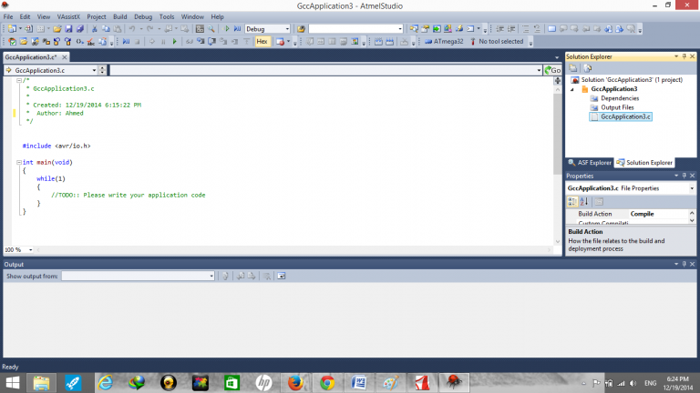
Working on Atmel Studio
- After downloading and installing o your computer, open the Atmel software.
- After opening, you can see the file option in the menu bar, click on the file, click ‘New’, and then select ‘project’.
- Write the program and save it.
- Add the respective header files for your program before calling the library functions.
- Include the library files (.c,.h) in your project.
- Now, remember to copy the library files into your project folder before introducing them to the project
- Browse the project folder and Add source and header files having extensions of .c and .h respectively.
- Then, you can see the included library files in Solution Explorer on the right-hand side.
- After that, compile the project by clicking on Build Solution from the Build menu. You can also press F7.
- Project compiles if there are no errors. And, If there is any error you need to fix that.
- Now, to select the programmer, Connect your programmer to your computer through a USB port. On the toolbar go to the tool option then select “STK500” from the toolbar and click on apply.
Example of Blinking Light LED Using AVR Microcontroller.
Here we are with the circuit through which you can kick-start learning the AVR. Hence we will make a blinking light LED circuit.
Components Required
| S.No | Components | Qty |
|---|---|---|
| 1. | ATmega32 | 1 |
| 2. | Resistors (1K, 10K) | 8, 1 |
| 3. | Capacitors (22pf) | 2 |
| 4. | LEDs | 8 |
| 5. | Crystal Oscillator | 1 |
Circuit Diagram

Code
#ifndef F_CPU

#define F_CPU 16000000UL //clock speed is 16MHz

#endif

#include <avr/io.h>

#include <util/delay.h>

int main(void) //main starts

{

       DDRD = 0b11111111; // declaring port D as output

    while(1) // initialize infinite while loop

    {

        PORTD = 0b10000000; // pin 0 of port D set HIGH

              _delay_ms(1000); // delay of one second

              PORTD = 0b01000000; // pin 1 of port D set
              _delay_ms(1000); // delay of one second

              PORTD = 0b00100000; // pin 2 of port D set

              _delay_ms(1000); // delay of one second

              PORTD = 0b00010000; // pin 3 of port D set

              _delay_ms(1000); // delay of one second

              PORTD = 0b00001000; // pin 4 of port D set

              _delay_ms(1000); // delay of one second

              PORTD = 0b00000100; // pin 5 of port D set

              _delay_ms(1000); // delay of one second
PORTD = 0b00000010; // pin 6 of port D set HIGH

              _delay_ms(1000); // delay of one second

              PORTD = 0b0000001; // pin 7 of port D set

              _delay_ms(1000); // delay of one second


    } // while loop end

} //main end
Working Explanation
First, you need to assemble the circuit. Connect the circuit according to the above-given diagram. After that, write the above-given code on your Atmel studio software. Compile and burn the code into your AVR IC. Give power to the circuit and you will observe the blinking of LEDs.
Applications of AVR microcontroller
We can widely use AVR microcontrollers in various industrial, commercial, and DIY projects. Some applications are:
- Digital signal processing.
- Touch screen.
- Home automation.
- Temperature control systems.


