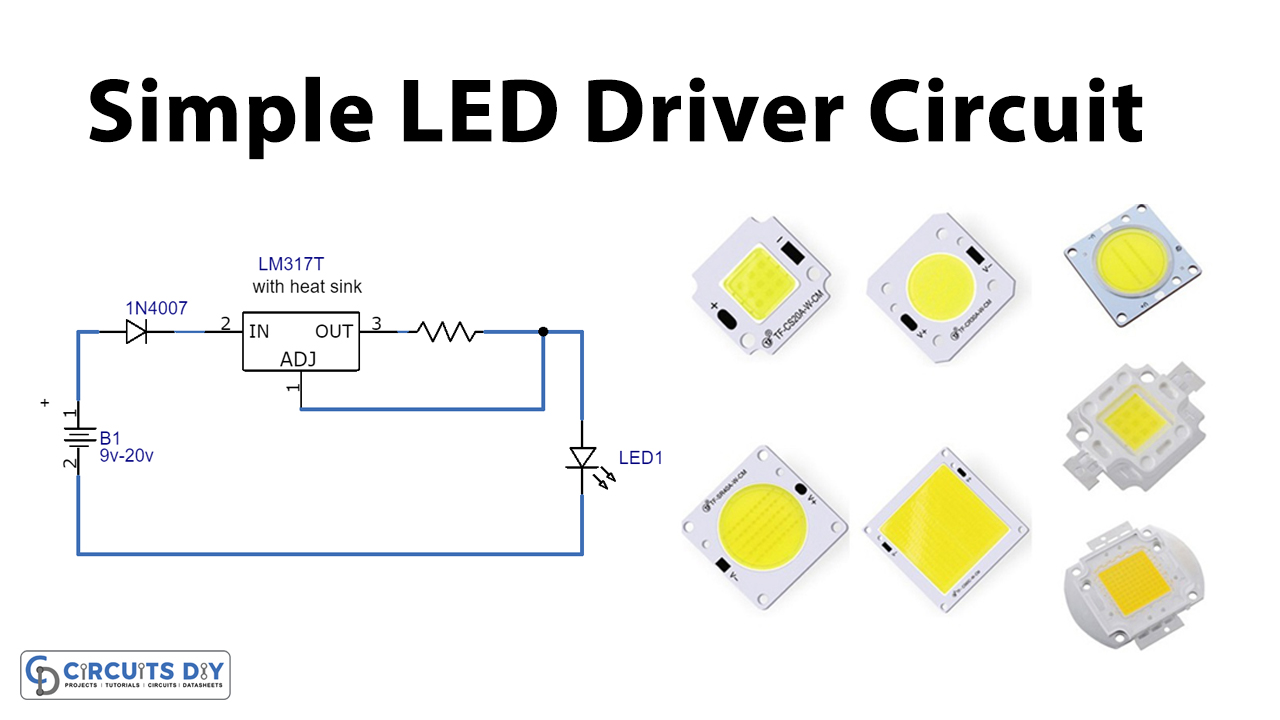
In this tutorial, we are going to make a simple LED driver circuit. This circuit is used to drive different kinds of high-power LEDs of different watts. This is a simple DIY project using an LM317T IC and a few passive components.
LM317T is a voltage regulator IC whose output can be varied using an external resistor. This is a monolithic integrated circuit which is an adjustable 3-terminal positive voltage regulator that supplies a load current of 1.5A with an adjustable output voltage over a 1.2V to 37V. It has internal current limiting, thermal shut-down, and safe area compensation. This IC is very old but it’s still very famous and useful, it can do much more than just voltage regulation. Its versatile circuitry allows you to use it not just as a voltage regulator but also as a current regulator. The output current of this is up to 1.5A, so you can easily drive any LED in this current range you just have to change the resistor according to your LED current requirements.
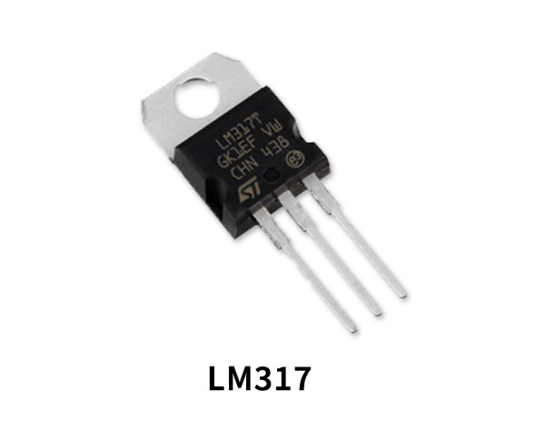
Hardware Components
The following components are required to make LED Driver Circuit
| S.no | Components | Value | Qty |
|---|---|---|---|
| 1. | Voltage Regulator IC | LM317T | 1 |
| 2. | Diode | 1N4007 | 1 |
| 3. | Resistor | – | 1 |
| 4. | LED | – | 1 |
| 5. | DC Supply | 9V to 20V | 1 |
LM317 Pinout
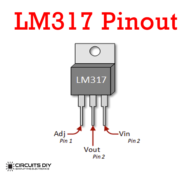
For a detailed description of pinout, dimension features, and specifications download the datasheet of LM317
LED Driver Circuit

Working Explanation
The LM317 is designed to accept an unregulated input voltage. The operating voltage of this particular circuit is 9 to 12 volts. There is a chart given above from which you can select the resistor (Rx) according to the LED you’ll use. When the voltage is applied to this circuit the IC’s output voltage and current can be altered and the desired current for turning the LED on is produced.
Applications and Uses
- Lightning purposes
- Used in Automobiles
- Decorative Purposes
- Can be used along with a doorbell to provide an indication

