In this tutorial, we are going to show you how to make a 555 LED flasher circuit. This project is ideal for beginners who want to get acquainted with basic circuit designing concepts. This circuit is very easy to build, its purpose is to flash LEDs which means turning them ON-OFF continuously. The IC that we are using is a 555 IC which is a timer IC, it creates pulses of current at specific time intervals depending on the RC (resistor-capacitor) connected with it.
With the help of the 555 timer IC the LEDs do not stay ON constantly, this IC creates pulses. LEDs turn ON at a pulse and then shut OFF after the pulse has passed, this process is repeated in a continuous cycle, therefore, it creates flashes of lights.

Hardware Components
The following components are required to make a 555 LED Circuit
| S.no | Components | Value | Qty |
|---|---|---|---|
| 1. | IC | NE555 timer | 2 |
| 2. | LEDs | – | 13 |
| 3. | Resistor | 10Ω, 100K, 10K, 150Ω | 12, 3, 1, 1 |
| 4. | Ceramic Capacitor | 1µF, 10nF | 1, 1 |
| 5. | Electrolytic Capacitor | 100µF | 1 |
| 6. | Battery | 3V | 1 |
NE555 IC Pinout

For a detailed description of pinout, dimension features, and specifications download the datasheet of 555 Timer
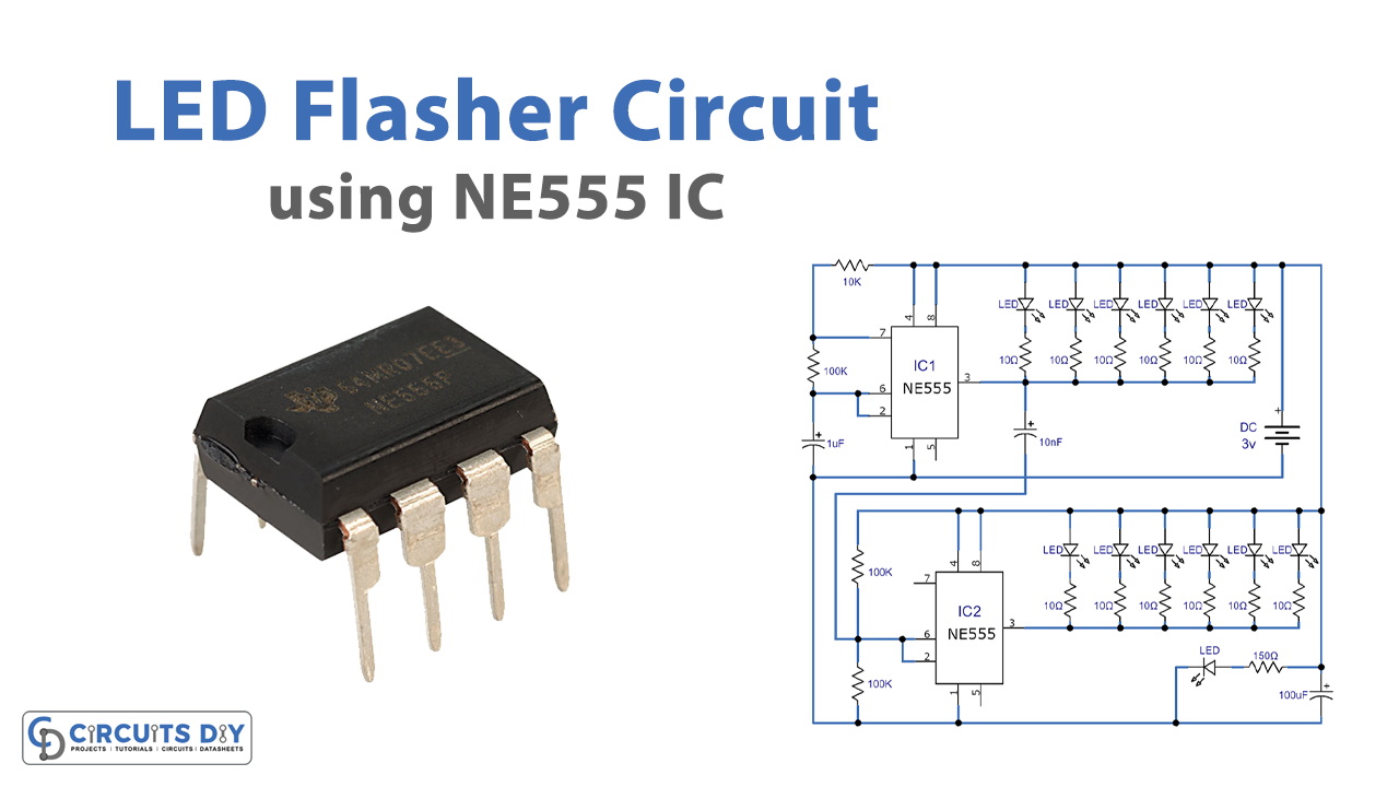
555 LED Circuit

Working Explanation
The operating voltage of this circuit is only 3 volts, its battery can last longer because this circuit has low current consumption. Let’s take a look at how this circuit works
Two 555 timer ICs are used, the upper one is used as a multivibrator and the lower one is working as a trigger pulse inverter. These ICs are connected in astable mode, in this mode, it will switch constantly between high and low. The output of this IC will generate a square wave from Pin 3, which is then sent to the array of LEDs and they will turn on for specific time intervals. These time intervals can be increased or decreased by changing the value of the capacitor used before the ICs.
Applications and Uses
- Lamp Dimmer
- Timer Switch
- Warning Devices
- Safety Blinkers
- Toys


