Introduction
In this blog, we’ll delve into the inner workings of the audio limiter circuit and explore how it can help you achieve optimal recording levels for your next project. We’ll take a closer look at how this circuit works, including its attack and decay times, and examine the various components that make it up.
But that’s not all. We’ll also discuss how to build your own audio limiter circuit and provide step-by-step instructions to guide you through the process. We’ll cover everything from selecting the right components to assembling the circuit and housing it in a light-proof box to protect it from ambient illumination.
So whether you’re a professional sound engineer, a musician, or simply someone who loves tinkering with electronics, this blog is for you. Get ready to expand your knowledge and skills and take your recordings to the next level with the power of the audio limiter circuit. Let’s get started!
What is an Audio Limiter Circuit?
An audio limiter circuit is a device that helps control the recording level of audio. It works by attenuating the input signal when it reaches a certain threshold level. This helps prevent the output level from becoming too high and causing distortion.
Hardware Required
| S.no | Components | Value | Qty |
|---|---|---|---|
| 1 | Polar Capacitor | 10u, 4u7, 100uF | 1, 1, 1 |
| 2 | Non Polar Capacitor | 470n | 2 |
| 3 | Transistor | 2N3904 | 2 |
| 4 | Resistor | 33k, 560k, 820k, 4k7, 2k2, 720R | 1 |
| 5 | Diode | TIL209, 1N34 | 1, 2 |
Circuit Diagram
How Does an Audio Limiter Circuit Work?
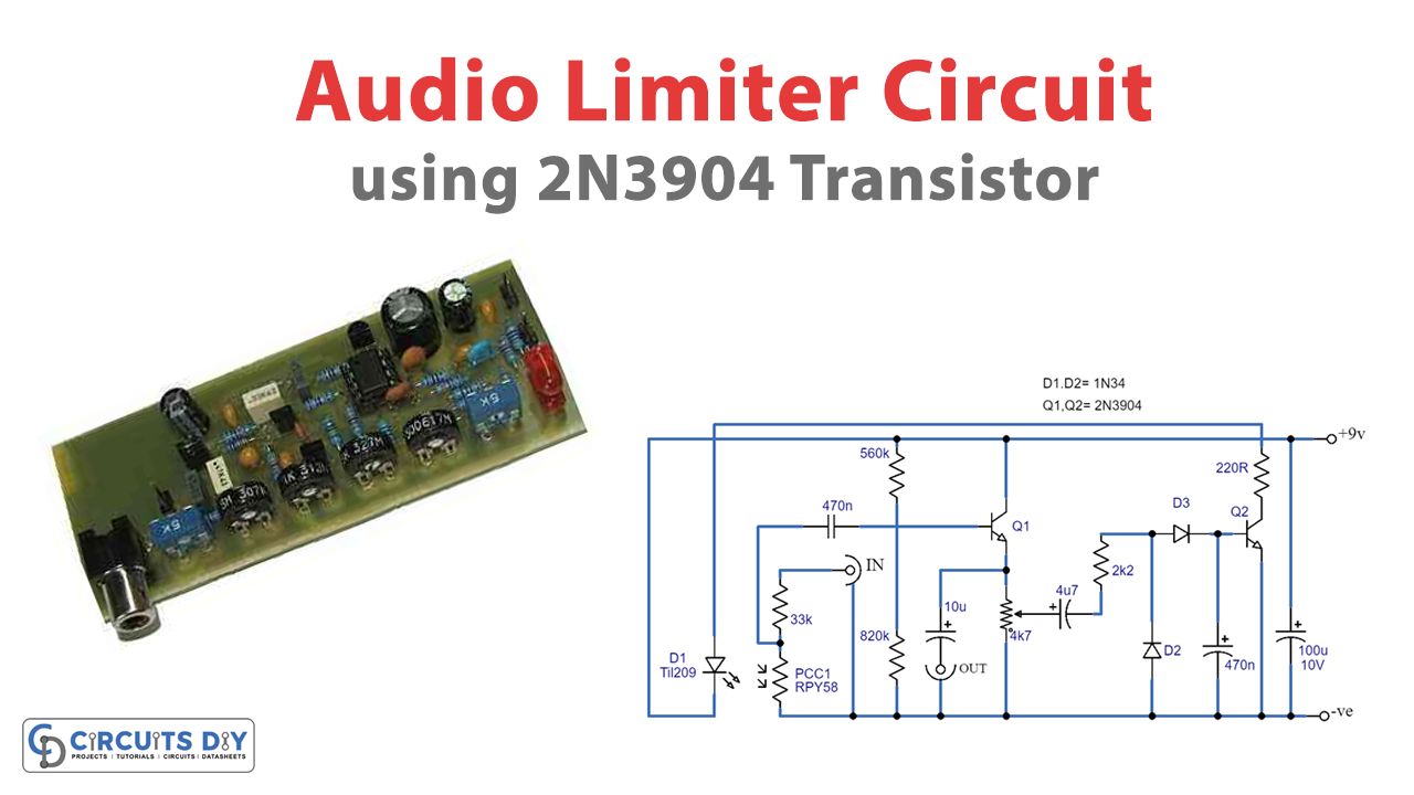
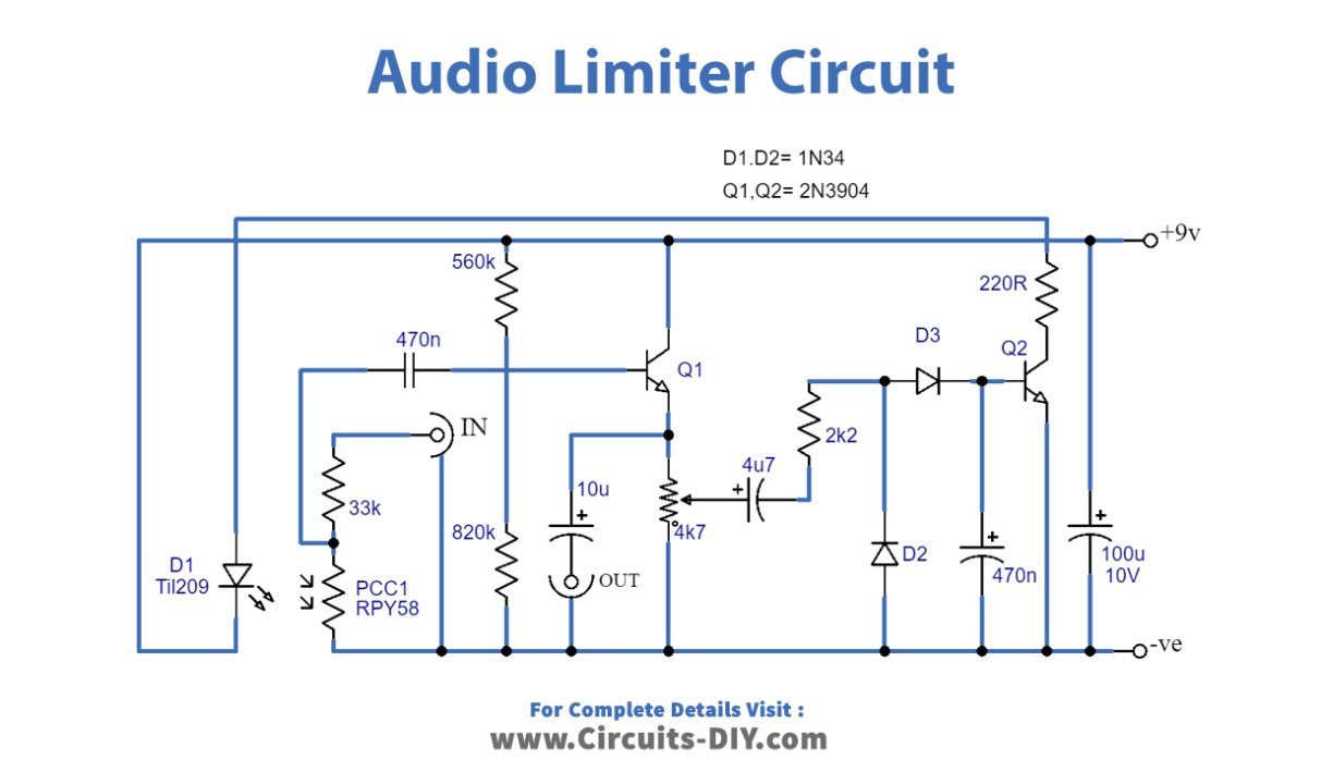
The audio limiter circuit consists of several components: an attenuator, emitter follower buffer stage, rectifier, and smoothing circuit. The input signal is first placed on an attenuator created through R1 and PCC1. Usually, PCC1 has a very high resistance, which can cause marginal failures with the attenuator.
The attenuated signal then feeds into the high input impedance of the emitter follower buffer stage, which helps prevent any loss of signal level. The input signal is then fed directly through to the output socket, with only a minor loss of amplitude.
If the input signal is strong enough, the positive bias created by the audio limiter circuit will activate Q2 and light up, generating diode D1, which is linked to its collector circuit. The light output from D1 is directed at the sensitive surface of PCC1, which causes a significant decrease in the resistance of PCC1.
This provides the desired attenuation of the signal, which helps prevent the output level from increasing too much. The higher the input signal is, the more strongly D1 glows and the greater the reduction in circuit gain.
Threshold Levels and Input Levels
In the audio limiter circuit prototype, the threshold level is around 230 mV, and raising the input level to 4 volts RMS triggers the output to increase to only around 320 mV. Higher threshold levels can be achieved by adjusting the slider of R4 to the appropriate point.
The attack and decay times of the circuit are both limited. It means that the unit responds quickly to changes in signal level and is generally not noticeable in operation.
Building the Unit
Building the audio limiter circuit should be pretty simple. But storing the unit in a light-proof box is essential to ensure that PCC1 is protected from ambient illumination. D1 and PCC1 should be installed as close together as possible. The current utilization of the audio limiter circuit is just around 1 to 5 mA, depending on the input level.
Conclusion
We hope you found this blog informative and helpful in achieving the perfect recording level. The audio limiter circuit is a powerful tool that can help you create high-quality recordings with minimal distortion. Understanding how this circuit works and learning how to build it yourself can take your recording game to the next level.
We encourage you to experiment with different components and settings to find the perfect balance for your needs. And if you have any questions or feedback, please don’t hesitate to reach out. We love hearing from our readers and are always happy to help.
Thank you for joining us on this journey of discovery and exploration. We hope you enjoyed reading this blog as much as we enjoyed writing it. Until next time, happy recording!

