Introduction
Welcome to the electronic siren circuit tutorial, where sound and technology merge to create a symphony of alarm. Whether you’re an emergency responder looking for a reliable siren or an electronics hobbyist looking for a new project, this guide will show you how to make different electronic siren circuits using various ICs (Integrated Circuits). From IC 7400 to the versatile 4017 decade counter, we’ll delve into the different ICs that can create a wide range of siren sounds. So, please put on your inventor’s hat and get ready to make some noise as we explore the exciting world of electronic siren circuits.
What is an Electronic Siren Circuit?
An electronic siren circuit is a device that uses electronic components to produce a loud and attention-grabbing sound similar to that of a traditional siren. With its versatility, reliability, and power, the electronic siren circuit is a vital tool for emergency responders and first responders, helping them to keep people safe and informed in times of crisis.
Hardware Required
Using CD4011 IC (Circuit Table)
| S no | Components | Value | QTY |
|---|---|---|---|
| 1 | IC | CD4011 | 1 |
| 2 | Capacitor C1, C2. C3. C4 | 0.015, 0.22, 0.5uF, 10pF | 1, 1, 1, 1 |
| 3 | Resistor R1, R2 | 150k, 500kΩ | 1, 1 |
| 4 | Transistor | BEL187 | 1 |
| 5 | Diode D1, D2 | 1N4148, 1N4001 | 1, 1 |
| 6 | Speaker | 8Ω | 1 |
| 7 | Jumper Wire | – | 1 |

Hardware Required
Using IC 4093 (Circuit Table)
| S no | Components | Value | QTY |
|---|---|---|---|
| 1 | IC | – | 3 |
| 2 | Polar Capacitor | 22u, 47u, | 1, 1 |
| 3 | Capacitor | 180n | 1 |
| 4 | Resistor | 82k, 100k, 470k, 47k, | 1, 2, 1, 1 |
| 5 | Variable Resistor | 1M | 1 |
| 6 | Transistor(MOSFET) | VN66AF | 1 |
| 7 | Speaker | 5W | 1 |
| 8 | Jumper Wire | – | 1 |
using IC 4093

Hardware Required
Using IC 7400 (Circuit Table)
| S no | Components | Value | QTY |
|---|---|---|---|
| 1 | IC 1 | – | 4 |
| 2 | IC 2 | – | 2 |
| 3 | Polar Capacitor | 220uF | 2 |
| 4 | Capacitor | 0.1, 0.2uF | 4, 2 |
| 5 | Resistor | 4K7, 470R | 6, 1 |
| 6 | Speaker | 8 – 150 OHM | 1 |
| 7 | Jumper Wire | – | 1 |

Working Explanations
Here’s the working explanation of all three simple electronic siren circuits.
Using CD4011 IC
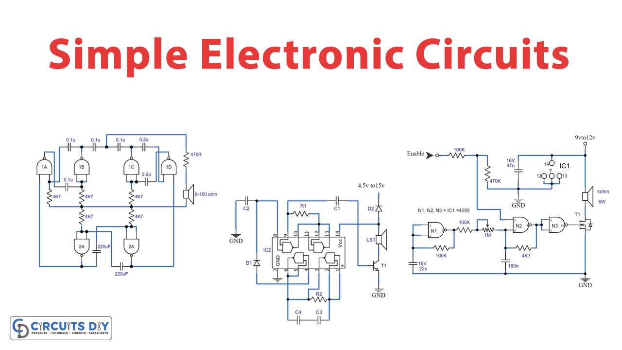
This circuit comprises a single chip called CD4011 (IC1), its foundation. When there is a high output from the low-frequency oscillator, the conduction D2 Diode in the circuit reacts by enabling the operation of the high-frequency oscillator. We can change the speed of the oscillator by increasing the value of the capacitor C3 to 8 microfarads.
This design uses the C1 capacitor and the R1 resistor to tone the different components of the changer. Additionally, we have used the C2 capacitor to enable the D1 diode to run at its maximum power. T1 transistor is a speaker driver in this circuit.
using IC 4093
Even though this circuit is cheap, it can make a lot of noise. This is possible because T1, an n-channel MOSFET, controls the loudspeaker.
CMOS logic circuits can directly drive MOSFETs. This kind’s output resistance, also known as the drain-source, is merely 3 ohms. Also, the drain current can go up to 1.7 A, and the drain-source voltage can go up to 40 V.
You can use a computer to run the circuit. Make the ENABLE input logic high to do this. You can also use a switch instead of a computer. When the Schmitt trigger N1 sees a high input at pin 5 of gate N2, it sends out pulses that make N2 oscillate. Through the buffer N3, the output of N2 affects the MOSFET. P1 is used to change how often N2 goes off.
Using IC 7400
The IC 7400 siren circuit consists of a pair of oscillators, each producing one of the tones. To provide a two-tone output, a third oscillator is used to turn on and off the remaining tones alternately. This provides the output. Modifying the values of the capacitors allowed to the production of various tones.
Final Words
These simple electronic siren circuits are a great way to generate a loud and attention-grabbing sound. You can use them for security systems, emergency vehicles, and industrial alarms, where loud and attention-grabbing sound is required to alert people. With creativity and experimentation, you can customize this circuit to suit your specific needs and make it even more efficient. If you have any query, feel free to ask in the comment section. Happy learning!


