Introduction
Are you ready to take your DIY projects to the next level? Look no further than building your own 3-phase brushless DC (BLDC) motor driver circuit. These motors are known for their high efficiency and reliability, making them perfect for a wide range of applications, such as electric vehicles and robotics.
With the proper guidance and determination, you will be well on your way to creating a circuit that will power your project to success. Trust us, the satisfaction of a job well done will make it all worth it. So, don’t wait; dive into the exciting world of BLDC motors and start building your own driver circuit today!
What is a 3-Phase Brushless (BLDC) Motor?
A brushless DC (BLDC) motor is an electric motor with a rotor equipped with surface-mounted permanent magnets and a stator similar to a traditional 3-phase stator seen in induction motors.
Since the commutator in a BLDC motor is electrical rather than mechanical, it is more reliable than a DC motor. The rotor magnets of a brushless DC (BLDC) motor produce the rotor’s magnetic flux, which results in greater efficiency. That’s why you’ll find BLDC motors in high-end white goods like pumps, fans, and other appliances that need to run reliably and efficiently.
Components Required
You will require the following hardware for 3-Phase Brushless (BLDC) Motor.
| S.no | Component | Value | Qty |
|---|---|---|---|
| 1. | Hall effect sensors | – | 3 |
| 2. | NOT gates | – | 3 |
| 3. | IC | IRS2330 | 1 |
| 4. | IGBTs | – | 6 |
| 5. | Current sensing stage | – | 1 (with resistive divider) |
| 6. | Power supply | – | 1 |
It’s important to note that these are just a summary of the components required, and you should refer to the circuit diagrams and connections for more detailed hardware requirements.
Steps to make a 3-Phase Brushless (BLDC) Motor Driver
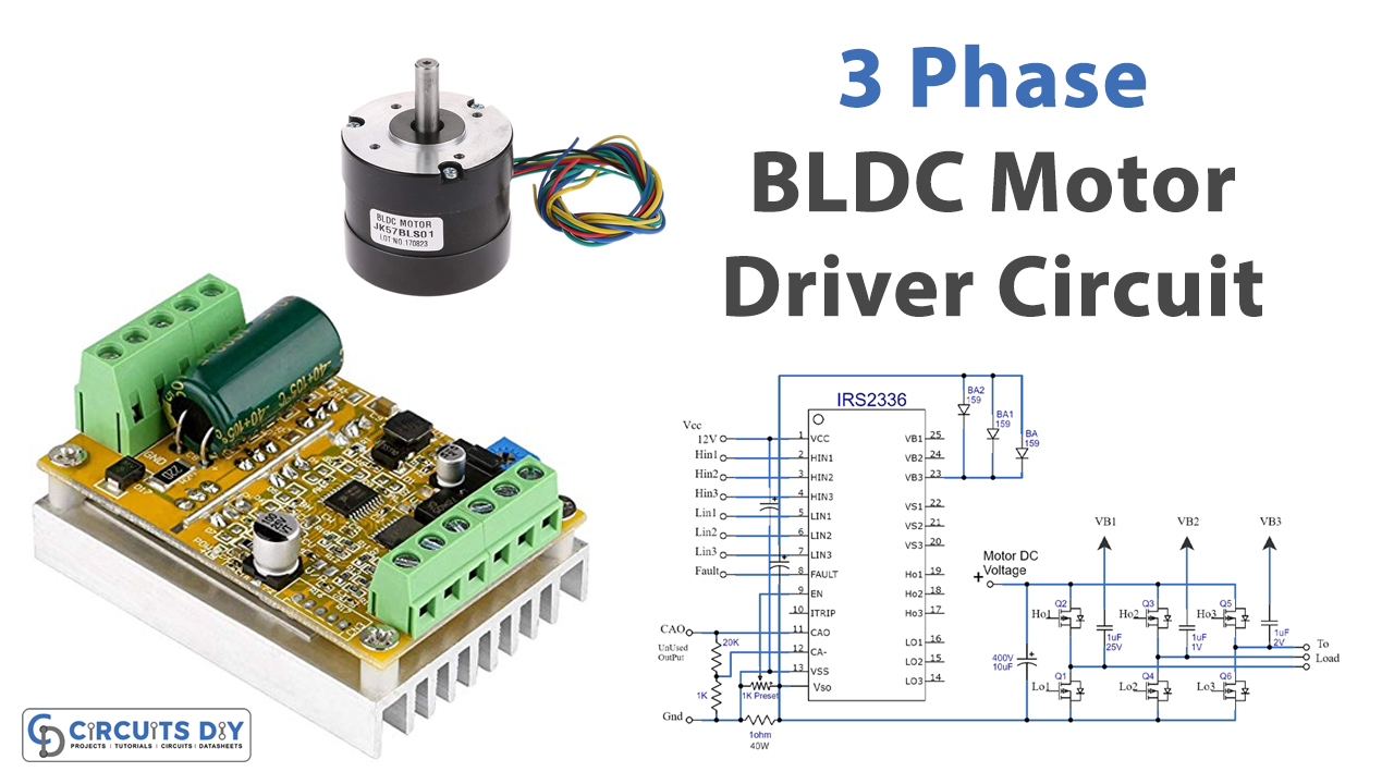
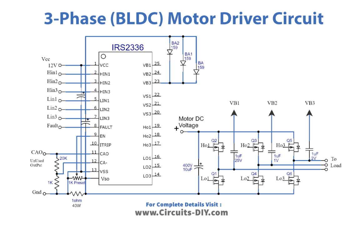
To make a 3-Phase Brushless (BLDC) Motor Driver, follow the given circuit diagram or connections
Circuit Diagram
Connections
- The Hall effect sensors are connected to the stator assembly and provide the control circuit with the necessary data to activate the stator coils in sequence.
- The negatives of all the hall sensors are grounded.
- The outputs of the Hall effect sensors are buffered by NOT gates and then connected to the inputs of the IC IRS2330.
- The IC IRS2330 is connected to a standard H-bridge configuration using 6 IGBTs.
- The circuit also includes a current sensing stage connected across the lower left section of the circuit.
- The resistive divider in the current sensing stage is connected to allow for over-current protection and control of the BLDC motor.
Working Explanation
The circuit uses the IRS2330 IC as the main driver. The IC pinouts are connected to external components, including a standard H bridge configuration using 6 IGBTs. This H bridge configuration drives the BLDC motor by controlling the current flow through the electromagnet coils.
The Hall effect sensors detect the rotor magnet’s position and provide the control circuit with the necessary data to activate the stator coils in sequence, creating a rotational torque and resulting in the intended rotational motion. However, before applying the hall sensor signals to the driver IC inputs, the signals need to be buffered utilizing several NOT gates. The outputs of the NOT gates are then properly incorporated with the inputs of the IC IRS2330.
The circuit also includes a current sensing stage, which is used for over-current protection and control of the BLDC motor. The resistive divider in this stage is dimensioned to allow for accurate current sensing and control.
In summary, the IRS2330 IC is connected to an H-bridge configuration of IGBTs, and hall effect sensors to control the stator coils; the hall sensor signals are buffered by NOT gates and then sent to the IC. A current sensing stage is also present in the circuit for the over-current protection of the motor.
Final Words
In conclusion, building a 3-phase brushless DC motor driver circuit can be a challenging task. Still, with the proper knowledge and components, it is possible to create a functional and efficient driver circuit. If you have any queries or comments, please feel free to reach out. Thank you for reading!

