Introduction
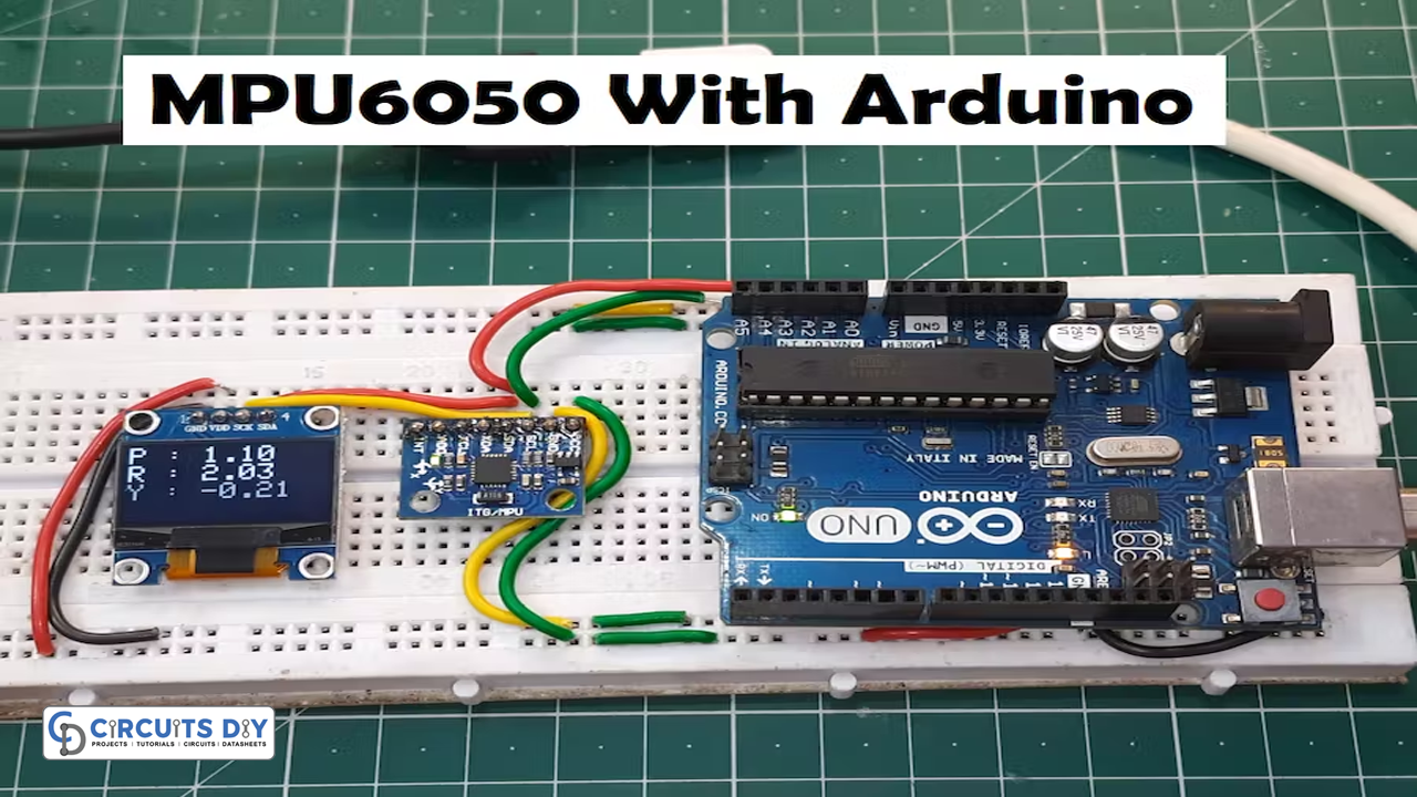
We often use it on our cellphones vertically, but what do we see when we click the rotate button? The visual turn horizontal. Similarly, while playing a game, we touch the screen to aim and move forward, backward, or left, respectively. This is caused by the gyro sensors embedded in modern smartphones, which are continually transmitting information to the display driver to shift the phone’s orientation from portrait to landscape or to allow player movement in several directions. So this tutorial would discuss the MPU6050 Gyroscope with Arduino
A gyroscope is a device that aids in orientation determination by utilizing the earth’s gravity. When it comes to cell phones, are known as gyro-sensors. They detect how quickly the item is rotating about its 3 axis
What is the MPU6050 Gyroscope?
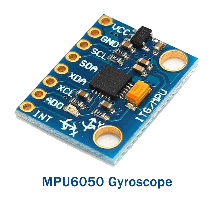
The MPU6050 sensor module is a 6-axis motion tracking device in just one. It comes in a tiny package with a 3-axis gyroscope, 3-axis accelerometer, and digital motion processor. . The MPU6050 gyroscope detects rotational speed along the X, Y, and Z axes.
Hardware Components
You will require the following hardware for MPU6050 Gyroscope with Arduino.
| S.no | Component | Value | Qty |
|---|---|---|---|
| 1. | Arduino UNO | – | 1 |
| 2. | Gyro Sensors | MPU6050 | 1 |
| 3. | 0.96″ OLED Display | 128X64 | 1 |
| 4. | Breadboard | – | 1 |
| 5. | Jumper Wires | – | 1 |
Steps Interfacing MPU6050 Gyroscope with Arduino
To interface the MPU6050 Gyroscope with Arduino, you need the above-given components. Once you have them all; follow the following steps:
Schematic
Make connections according to the circuit diagram given below.

Wiring / Connections
| Arduino | Gyro Sensors | OLED LCD |
|---|---|---|
| 5V | VCC | VCC |
| GND | GND | GND |
| A4 | SDA | SDA |
| A5 | SCL | SCL |
Installing Arduino IDE
First, you need to install Arduino IDE Software from its official website Arduino. Here is a simple step-by-step guide on “How to install Arduino IDE“.
Installing Libraries
Before you start uploading a code, download and unzip the following libraries at /Progam Files(x86)/Arduino/Libraries (default), to use the sensor with the Arduino board. Here is a simple step-by-step guide on “How to Add Libraries in Arduino IDE“.
Code
Now copy the following code and upload it to Arduino IDE Software.
#include <Wire.h>
#include <Adafruit_GFX.h>
#include <Adafruit_SSD1306.h>
#include <MPU6050_light.h>

#define SCREEN_WIDTH 128 // OLED display width, in pixels
#define SCREEN_HEIGHT 64 // OLED display height, in pixels
// Declaration for an SSD1306 display connected to I2C (SDA, SCL pins)
Adafruit_SSD1306 display(SCREEN_WIDTH, SCREEN_HEIGHT, &Wire);


MPU6050 mpu(Wire);
unsigned long timer = 0;

void setup() {
  Serial.begin(115200);                           // Ensure serial monitor set to this value also
  if(!display.begin(SSD1306_SWITCHCAPVCC, 0x3C))  // Address 0x3C for most of these displays, if doesn't work try 0x3D
  {
    Serial.println(F("SSD1306 allocation failed"));
    for(;;);                                      // Don't proceed, loop forever
  }
  display.setTextSize(1);
  display.setTextColor(SSD1306_WHITE);            // Draw white text
  display.clearDisplay();
  Wire.begin();
  mpu.begin();
  display.println(F("Calculating gyro offset, do not move MPU6050"));
  display.display();
  mpu.calcGyroOffsets();                          // This does the calibration
  display.setTextSize(2);
}

void loop() {
  mpu.update();
  if((millis()-timer)>10)                         // print data every 10ms
  {
    display.clearDisplay();                       // clear screen
    display.setCursor(0,0);
    display.print("P : ");
    display.println(mpu.getAngleX());
    display.print("R : ");
    display.println(mpu.getAngleY());
    display.print("Y : ");
    display.print(mpu.getAngleZ());
    display.display();                            // display data
    timer = millis();
  }
}
Let’s Test It
After uploading the code, It’s now time to test the circuit. Once you powered up the Arduino, the readings would come up on the screen. Rotate the circuit a little and you will see changes in their readings
Working Explanation
You need to understand the code to understand the working of the circuit.
- First, you need to include the libraries for the sensor and the display we are using in this project. Also, include the wire library to communicate with the external 12C device.
- Then define the pins of an Arduino connected to the display and name them
- Create an object display for the SS1306 display
- Now create Adafruit_MPU6050 object mpu to access related functions.
- In the void setup, use the begin functions to initialize the serial communication. Then provide the condition that if allocation got failed, the code could not proceed further. Otherwise, give a function to set text size and color. Then clear the display so that the coming readings would be shown on the screen.
- Now for the calibration, we calculate the offset by using mpu.calcGyroOffsets function
- In the void loop, we take the data and print that aster every 10ms
Applications
- Tilt sensors
- Orientation detectors
- Robotics applications; etc
Conclusion.
We hope you have found this MPU6050 Gyroscope with Arduino Circuit very useful. If you feel any difficulty in making it feel free to ask anything in the comment section.

