In this tutorial, we are going to make a “Voltage Follower Circuit Using op-amp 741o Amplifier Circuit”.
A voltage follower is a unity-gain, noninverting buffer that requires only an operational amplifier (and a decoupling capacitor). It is simply a circuit in which output follows the input, which means output voltage remains the same as input voltage. An op-amp used in a voltage-follower configuration must be specified as “unity-gain stable”. It is also commonly known as Unity gain Op-amp Amplifier or Op-amp Buffer.
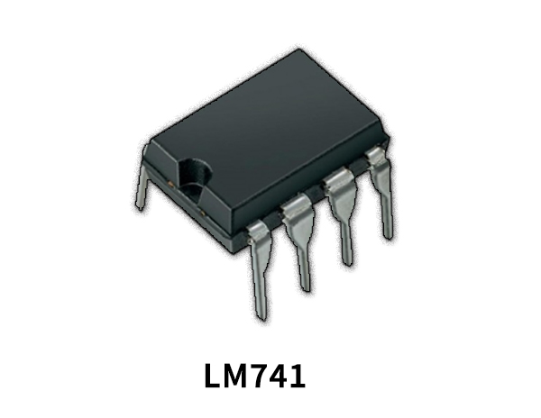
We design a simple Voltage Follower Circuit by using op-amp 741 to give unity gain output. As We said earlier the voltage follower circuit will give the output the same as the input signal but the output gain only increases. IC 741 is a dual inline packed 8 Pin integrated circuit. It can provide high grain output. It has two input terminals called Inverting input (Pin 2) and Non-Inverting input (Pin 3) and then one output terminal (Pin 6).
Hardware Components
The following components are required to make a Voltage Follower Circuit
| S.no | Component | Value | Qty |
|---|---|---|---|
| 1. | Operational Amplifier IC | LM741 | 1 |
| 2. | Variable Resistor | 10KΩ | 1 |
| 3. | Resistor | 1KΩ | 1 |
| 4. | Input Signal Source (Use function generator) | – | 1 |
| 5. | Connecting Wires | – | – |
| 6. | Power Supply | 9V | 1 |
LM741 Pinout
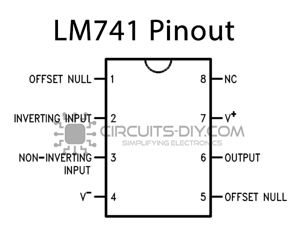
For a detailed description of pinout, dimension features, and specifications download the datasheet of LM741
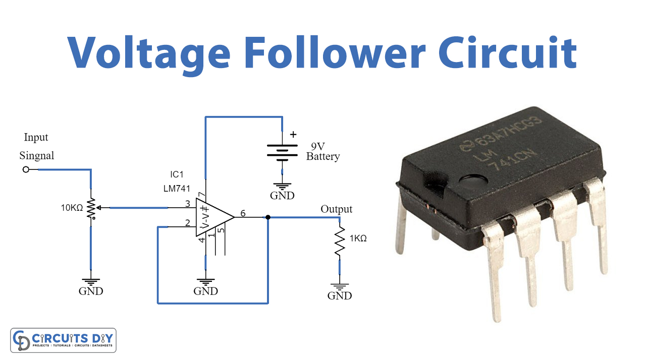
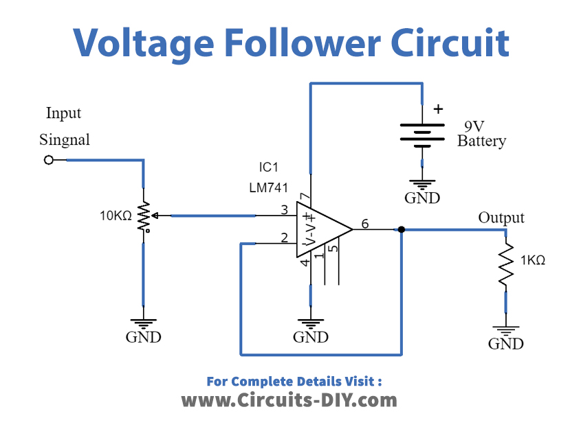
Voltage Follower Circuit
Working Explanation
As shown in the Circuit, variable input is given to the non-inverting (Pin3) terminal of the op-amp and the inverting (Pin2) terminal is given the negative feedback from the output (Pin6). By adjusting the potentiometer at the input, Vs can be varied to a different value in the range of 0-9Vdc. Bias pins are connected to the battery and the output is connected to the 1KΩ Load resistor. As it’s a Unity gain amplifier means the gain of the amplifier will be 1 and whatever is fed as input, can be received as output.
The input impedance of operational amplifier IC 741 will be very high, sometimes the input impedance is much higher (up to 1MΩ) Due to the high input impedance we can apply weak signals across the input and a very low current will be drawn from the input source and then gives high current output to the load. On the other hand, the output impedance is very low, and it will produce the same signal input, in the output

We can calculate current, Voltage, and Resistance by using following ohm’s law.
Current = Voltage / Resistance
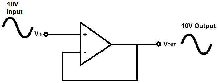
Here the voltage follower gives the same output voltage as input voltage but it draws a low input current from the input source. Due to high input impedance, the input current is much lower than the output current while the output voltage follows the input. So, the voltage follower provides a large power gain across its output. voltage follower circuit is used to create isolation between two different kinds of circuits.
Applications
A voltage follower is used as a buffer circuit and can be used to isolate stages while building multistage filters or some other multistage circuit.

