In this tutorial, we are going to make an “H-Bridge Motor Driver Circuit L293D”.
A motor is the most commonly used actuator in an electronic device/machine. As Arduino microcontrollers or PIC microcontroller has an operating voltage of 5V or 3.3V, a decent DC motor requires 5V or 12V to operate. In this case, if we want to supply the power to the motor, we need a high voltage. But we know that microprocessor output is low, and it cannot give enough power from its I/O pin to drive a motor. To supply this voltage/current from the microprocessor to the motor, we need a Motor driver between our motor and controller.
An H-Bridge driver is quite popular in driving loads such as brushed DC motors and it is widely used in robotics and industry. The main advantages of using an H-Bridge driver are high efficiency, rotation direction change, and turning off the motor’s H-bridge topology which we used the L293D motor driver IC. This IC can drive inductive loads such as motors, Relays, Solenoids, and bipolar stepper motors. It has Internal ESD protection, High noise immunity inputs, and a wide supply voltage range of 4.5V to 36V.

Hardware Components
The following components are required to make H-Bridge Motor Driver Circuit
| S.no | Component | Value | Qty |
|---|---|---|---|
| 1. | Diode | 1N4001 | 4 |
| 2. | IC | L293D | 1 |
| 3. | Connecting wires | – | 1 |
| 4. | Battery | 12V, 5V | 1 |
L293D IC Pinout
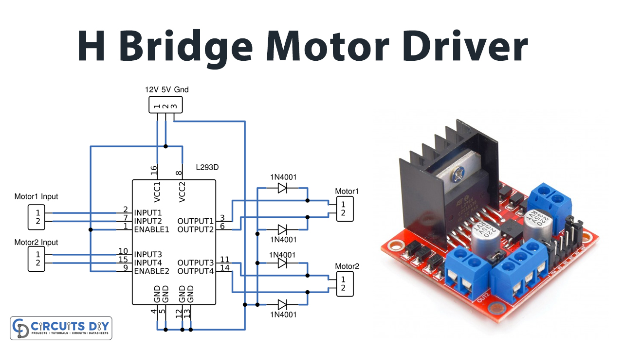
H-Bridge Motor Driver Circuit

Working Explanation
We know an H-Bridge is a circuit that switches the polarity of a voltage applied to the load (here load is a motor), Hence we can change the rotating direction of the motor. Here H-Bridge Motor driver coordinates the supply signal to the load motor and drives it accordingly. IC L293D is a quadruple high current half-H driver, capable of providing bidirectional drive currents up to 600mA at 4.5V to 36V voltages.
This circuit is designed to drive two separate motors by using two inputs. Motor 1 input signal is applied to 1A, and 2A pins of L293D, and output are taken from 1Y and 2Y Pins. Motor 2 input signal is applied to 3A, and 4A pins of L293D and output is taken from 3Y, and 4Y pins. The motor driver receives signals from the microprocessor and eventually, it transmits the converted signal to the motors. It has two voltage pins (VCC1 and VCC2), and one of them is used to turn on the motor driver, and another pin is used to apply the voltage to the motor through this motor IC. This IC will continuously toggle the output signal according to the input wave it is receiving from the microprocessor. Here D1 – D4 Diodes are used as Reverse voltage protection from motors.
Applications
- It is widely used in robot servos and conveyor operations.
- It is used in different types of drones to regulate the speed and applications such as surveillance and terrain navigation.
- It is used in AC to DC converters motor drivers.

