Introduction
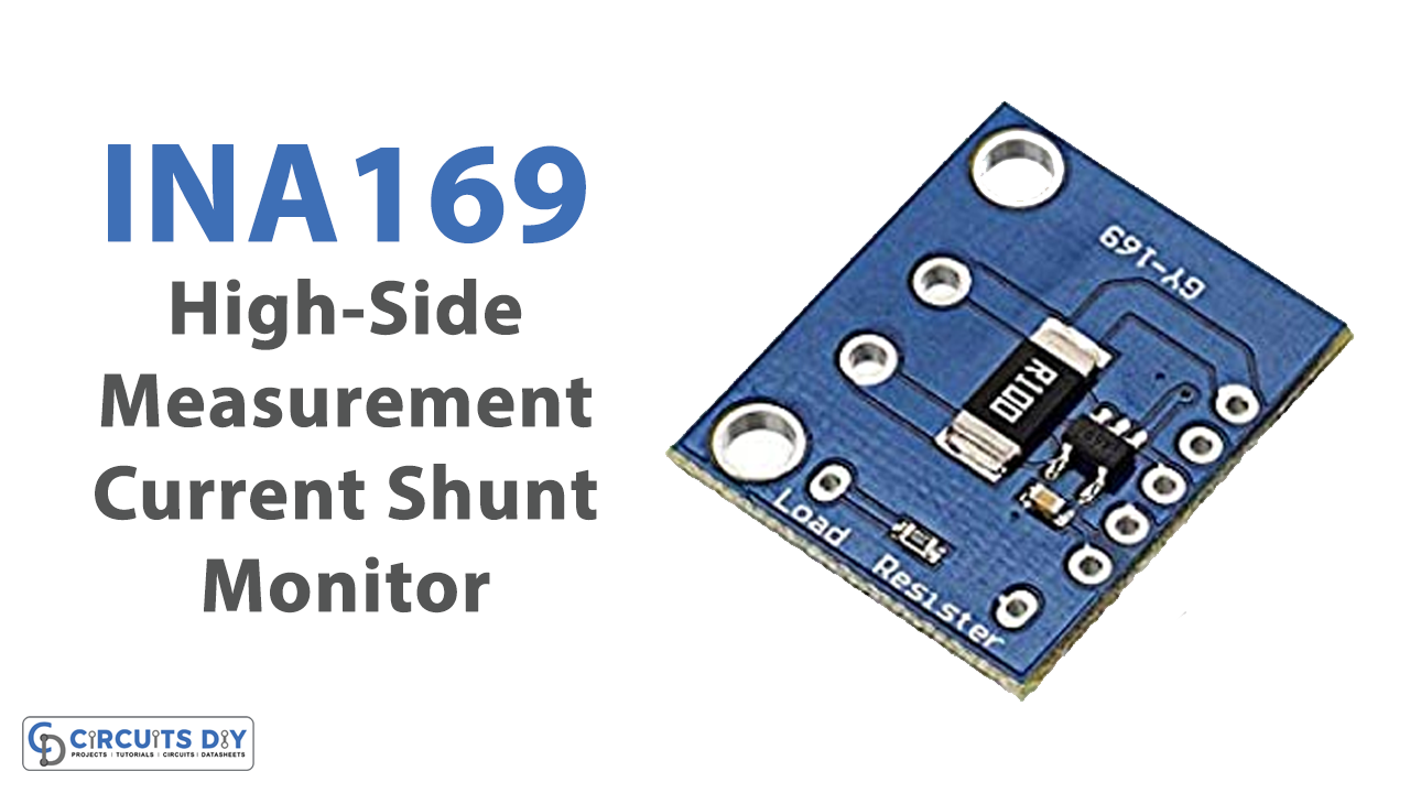
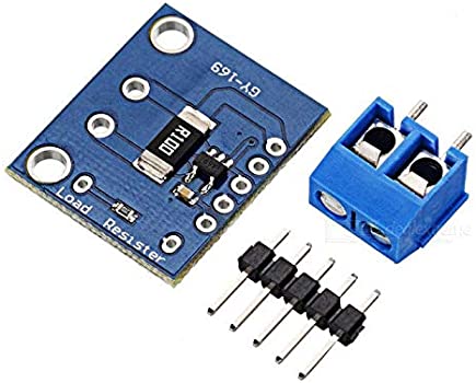
GY-169 is a simple current converter for current measuring up to 5A. It incorporates the INA169 chip delivered by Burr-Brown from Texas Instruments, which intensifies the voltage read by a little shunt and gives a voltage yield relative to the deliberate current. The 0.1 ohms, 2W resistor permits an exact current estimation up to 5A with a 1V proportion for every Ampere. You can just interface the module with the microcontroller to control or monitor the current of any device.
Gy-169/ INA169 Board Overview
The breakout board comprises a shunt resistor, the INA169 chip, and a load resistor. While shunt and load may seem to have two resistors, just one is inhabited on the board. Assuming you might want to change the values of the resistors, you can change them by putting different values of resistors in parallel.
Working of Module
As current goes from VIN+ through the shunt resistor to VIN-, it makes a voltage drop across the shunt. The operation amplifier within the INA169 chip estimates the difference between the VIN+ and VIN-voltages and provides results based on that. It amplifies the output through the inside transistor, which sources a current out of the INA169 chip. As that current goes through RL to the ground, it generated a voltage level at VOUT.
Features and Specifications of Gy-169/ INA169
Features
- Complete Unipolar High-Side Current
- Measurement Circuit
- Wide Supply and Common-Mode Range
- Independent Supply and Input Common-Mode Voltages
- Single Resistor Gain Set
- Low Quiescent Current
- 5-Pin, SOT-23 Packages
- Number of channels: 1
- Comparators : 0
Specifications
- Chip: INA169
- Shunt resistor 0.1 ohm 1% 2W
- Supply voltage: 2.7 ⁓60 V
- Current measurement up to + 5A
- Output: 1V for each Ampere measured
- Common mode voltage (Max): 60V
- Common mode voltage (Min): 2.7V
- Input offset (+/-) (Max): 1000uV
- Input offset drift (+/-):1uV/C
- Gain: Adjustable
- Gain error: 2%
- Bandwidth: (kHz)440
- Iq (Max): 0.125mA
- Operating temperature range: (C)-40 to 125
Pinouts of INA169
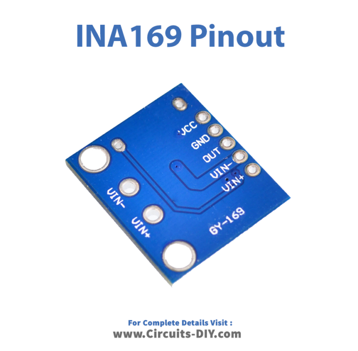
| Pin Name | Description |
| Vcc | Supply power to the module needs to be connected to 3.3V, 5V, etc. This can be anywhere from 0 to 60V |
| GND | The ground. Should be connected to the ground. |
| VIN+ | Positive input voltage. Needs to be connected to the positive side of the supply |
| VIN- | Negative input voltage. |
| OUT | Output current |
Gy-169/ INA169 Interfacing with Arduino
To interface the module with Arduino, you need to utilize a jumper wire to associate the INA169 VCC and VIN+ pins, as we need to control the load with the Arduino 5V. If you utilize an alternate power source, i.e, other than the Arduino 5V or 3.3V through VIN+ and VIN-, ensure you associate the ground of the power source to the ground of the INA169 board. Simply guarantee that the voltage level as estimated from VIN+ to ground doesn’t surpass 60V. Otherwise, it would create harm for individuals and the environment.
Applications of Gy-169/ INA169 Module
Battery Chargers
Cell phones, tablets, and different sorts of versatile gadgets are requiring progressively more modest structures with lower power consumption. They are additionally turning out to be substantially more complicated. These current sensors help to solve power consumption problems by measuring the current.
Other Applications
- Automotive applications.
- Computers.
- Precision Current Source
- Cellphones
- Power management, etc

