In this tutorial, we are going to Make an “MPU9250 9-DOF MEMS Sensor Module Interfacing with Arduino”
Overview of MPU6050 Sensor
Micro-Electro-Mechanical System MPU6050 includes a three-axis accelerometer and a three-axis gyroscope. We can quantify things like displacement, acceleration, and other motion-related characteristics thanks to it.
The Digital Motion Processor (DMP) of the MPU6050 can solve complicated calculations. For interacting with Arduino, this module uses the I2C module.
Hardware Overview
The pull-up resistors, LDO, decoupling capacitors, pull-up resistors, and I/O headers make up the MEMS Sensor module. The sensor features an MPU9250 processor chip, which does all processing and includes an accelerometer, gyroscope, and magnetometer. It also contains the I/O Headers, which are used to connect to the microcontroller unit and transmit data to it. For the I2C Bus, pull resistors are positioned to source current and create a default state. To lower the voltage to 3.3V for the IC to work and improve power efficiency, an LDO voltage regulator is offered. Decoupling capacitors are used to clean the signals of unwanted noise.
Pin Configuration
| Pin Name | Function |
|---|---|
| Pin Name | Function |
| INT | Interrupt pin |
| ECL | I2C Master Serial Clock for external sensors connection pin |
| AD0/SDO | I2C Address/Serial data out pin |
| FSYNC | Frame Synchronization input pin |
| VCC | Power supply pin |
| GND | Ground pin |
| EDA | I2C Serial Data input for external sensors connection pin |
| nCS | Chip selection pin |
| SCL/SCLK | I2C Serial Clock/SPI Serial Clock pin |
| SDA/SDI | I2C Serial Data/SPI Serial Data pin |
Hardware Required
| S.no | Component | Value | Qty |
|---|---|---|---|
| 1. | Arduino UNO | – | 1 |
| 2. | USB Cable Type A to B | – | 1 |
| 3. | DOF MEMS Sensor Module | MPU9250 9 | 1 |
| 4. | Jumper Wires | – | – |
Circuit Diagram
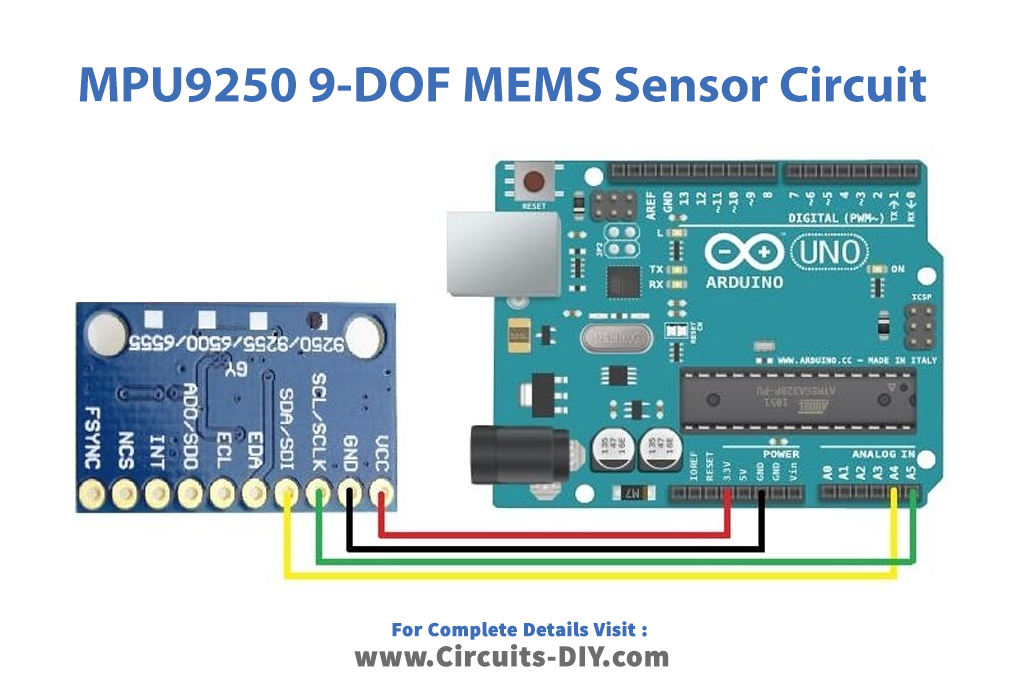
Connection Table
| Arduino UNO | MPU9250 9-DOF MEMS Sensor Module |
|---|---|
| GND | GND |
| 3.3v | Vcc |
| A4 | SDA |
| A5 | SCL |
Arduino Code
#include "MPU9250.h"

// an MPU9250 object with the MPU-9250 sensor on I2C bus 0 with address 0x68
MPU9250 IMU(Wire,0x68);
int status;

void setup() {
  // serial to display data
  Serial.begin(115200);
  while(!Serial) {}

  // start communication with IMU
  status = IMU.begin();
  if (status < 0) {
    Serial.println("IMU initialization unsuccessful");
    Serial.println("Check IMU wiring or try cycling power");
    Serial.print("Status: ");
    Serial.println(status);
    while(1) {}
  }
}

void loop() {
  // read the sensor
  IMU.readSensor();
  // display the data
  Serial.print("AccelX: ");
  Serial.print(IMU.getAccelX_mss(),6);
  Serial.print("	");
  Serial.print("AccelY: ");
  Serial.print(IMU.getAccelY_mss(),6);
  Serial.print("	");
  Serial.print("AccelZ: ");
  Serial.println(IMU.getAccelZ_mss(),6);

  Serial.print("GyroX: ");
  Serial.print(IMU.getGyroX_rads(),6);
  Serial.print("	");
  Serial.print("GyroY: ");
  Serial.print(IMU.getGyroY_rads(),6);
  Serial.print("	");
  Serial.print("GyroZ: ");
  Serial.println(IMU.getGyroZ_rads(),6);

  Serial.print("MagX: ");
  Serial.print(IMU.getMagX_uT(),6);
  Serial.print("	");
  Serial.print("MagY: ");
  Serial.print(IMU.getMagY_uT(),6);
  Serial.print("	");
  Serial.print("MagZ: ");
  Serial.println(IMU.getMagZ_uT(),6);

  Serial.print("Temperature in C: ");
  Serial.println(IMU.getTemperature_C(),6);
  Serial.println();
  delay(200);
}
Working Explanation
Using the circuit diagram, connect the MPU6050 accelerometer and gyroscope sensor to an Arduino UNO. Start the Arduino IDE. Paste the code thereafter you copy it. Put it on your Arduino UNO now. Turn the sensor module as you like in three dimensions, and the serial monitor displays the readings. To see the various readings, adjust the module sensor’s directions.
Code Explanation
- Adding the header files is always the initial step in programming a code in Arduino. To connect the MPU9250 9-DOF MEMS Sensor Module to the Arduino, include the relevant header file. On the I2C Bus, an object called IMU is created with the address 0x68. The MPU9250 sensor is used to store the data, act on it, and then provide the appropriate readings.
- In the void setup, The Serial monitor is first initialized at a baud rate of 11520 bps. The execution cycle stops and the program is terminated if somehow the Serial monitor doesn’t start and no values are seen. The state of the IMU object is then checked using the variable status, which is then defined. The Serial Monitor will show the phrases “IMU startup failure,” “Check IMU wiring or attempt cycling power,” and then report the value stored in status if the status is less than 0 i.e. no voltage is received. The while(1) statement makes this a permanent condition, thus the code won’t continue until the status value is higher than 0.
- When the IMU status is greater than 0, the execution cycle moves into the void loop block. The readSensor function in the loop would read the IMU (). They examined the magnetometer, gyroscope, and accelerometer readings. Through the functions getAccelX mss(), getAccelY mss(), and getAccelZ mss(), the acceleration value in mG for each axis is read and presented on the Serial monitor. The value will be shown with a maximum of six decimal places. GetGyroX rads(), getGyroY rads(), and getGyroZ rads() are used to read the angle measurement in radians per second in the x, y, and z axes, respectively, and show it on the Serial monitor. Furthermore, the figure will be shown with up to six decimal places. Similar to this, the getMagX uT(), getMagY uT(), and getMagZ uT() functions read the value of the magnetic field strength in Tesla in the x, y, and z axes, respectively, and show it in the Serial monitor. Additionally, the figure will be shown with up to six decimal places. Finally, it will use getTemperature C() to obtain the temperature measurement in six decimal places.
Application and Uses
- Gaming devices
- Robotic applications
- Health and fitness devices
- Tilt sensing devices, etc