Introduction
In this tutorial, we are going to make a “High Impedance Preamplifier using a Transistor”. Impedance is one of the characteristics of electrical components that measure resistance to a current. However, impedance can be high medium, or low. Here, we are working to get high impedance.
An output device’s ability to create sound is directly impacted by impedance. Thus, high impedance is excellent for some audio amplifiers. For example, for headphones. Lower impedance may sound OK for general listening but struggle to play higher treble or deeper bass. The amplitude may become distorted at both extremes of the frequency range. High-impedance headphones are free of distortion and provide a clearer audio projection.
Hardware Required
| S.no | Component | Value | Qty |
|---|---|---|---|
| 1. | NPN Transistor | BC549 | 1 |
| 2. | Resistor | 1M, 4.7K, 100 ohm | 1, 1, 1 |
| 3. | Electrolytic Capacitor | 10uF, 100uF | 1, 1 |
| 4. | Ceramic Capacitor | 0.1uF | 1 |
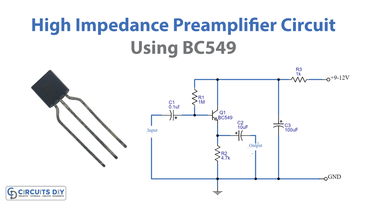
Circuit Diagram

Working Explanation
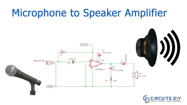
This High Impedance Preamplifier circuit follows the emitter follower configuration where input is fed through the base of the transistor and the output is taken at the emitter pin. So, the input is given at the base pin of the transistor. And, the power supply is given to the collector pin through resistor R3 and capacitor C3. Also, supplying Q1 with the bias current through R1. Across Resistor R2 we connect the load and take the output. The output voltage is just above unity, and the output impedance is around 1,000 ohms.
Application Uses
- For better sound quality of headphones.
- Applications where high impedance, lower distortion, or high-frequency signal is required.