Introduction
In this tutorial, we are going to “Design Crystal Oscillator Circuit.” Electronic oscillators are devices that produce periodic oscillating electronic signals. A crystal oscillator is an electronic device constructed of piezoelectric material that uses the mechanical resonance of a vibrating crystal to create an electrical signal with a specific frequency. Despite the fact that these oscillators can use a variety of piezoelectric resonators, most often quartz crystal is employed. These oscillator electrical circuits are hence known as crystal oscillators.
On the basis of the inverse piezoelectric effect, crystal oscillators work by applying an alternating voltage to the crystal’s surfaces, which causes the crystal to vibrate at its natural frequency. These vibrations are what ultimately transform into oscillations.
Hardware Required
Circuit Diagram


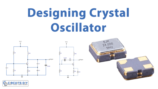
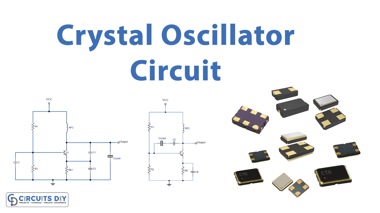
Series and Parallel Resonance Crystal Oscillator
In the above-given diagram, you can see there are two circuits:
- Series Resonance crystal oscillator
- Parallel Resonance crystal oscillator
Series Resonance Crystal Oscillator
Series capacitance CS and series inductance LS resonate at a frequency known as the series resonance frequency or fs. Because the crystal impedance will be lowest at this point, the amount of feedback will also be highest. The same is expressed mathematically as:

To build a series resonance crystal oscillator, connect the crystal element and coupling capacitor to the collector and base terminals of a common emitter configured, and obtain the oscillator output from the collector terminal.
Parallel Resonance Crystal Oscillator
When the reactance leg equals the reactance of the parallel capacitor Cp, the LS and CS resonate with Cp. This is known as the parallel resonance frequency or fp. The crystal impedance will be at its peak at this time, and as a result, the feedback will be at its lowest. In mathematics, it may be expressed as

The transistor is set up as a common emitter in a parallel resonance crystal oscillator circuit where the crystal element is positioned between the collector and emitter terminals and the output is taken from the collector terminal.
Working Explanation
Series Resonance Crystal Oscillator
The voltage divider circuit in these circuits is formed by resistors R1 and R2, and the circuit is stabilized by the emitter resistor RE. Additionally, CE in first serves as an AC bypass capacitor, while CC is employed to stop the transmission of DC signals between the collector and base terminals.
Parallel Resonance Crystal Oscillator
In the example of the second circuit, the capacitors C1 and C2 now create the capacitive voltage divider network. A Radio Frequency Coil (RFC) is also present in the circuits, which has the twin benefits of providing even DC bias and preventing the circuit output from being impacted by the AC signal on the power lines.
Application and Uses
- Communication system
- Commercial applications
- Digital systems
- Industrial applications
- Automotive applications; etc, etc