Introduction
If you have a laptop or smartphone, you might have used the application that adjusts the audio which gives you a good listening experience. This is an audio equalizer application. The frequency response of an audio signal is adjusted using an audio equalization circuit. Audio Equalizers are hardware filters that change how loud certain frequencies are. It varies the amplitude of distinct frequencies in a recording to change how loud each one is. As a result, an audio equalizer calculates how much each frequency contributes to the overall sound of a recording. To understand this, in this tutorial, we are going to make an “Audio Equalizer Circuit”.
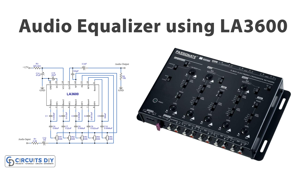
The circuit uses the IC LA3600. The LA3600 is a single integrated Op-amp with a single operational amplifier and a graphic equalizer with five bands for one channel. By connecting two LA3600, we can make ten equalizers, each of which can regulate various frequency bands. The LA3600 can be powered from 5 to 15 volts DC and is exceptionally stable when used with capacitive loads.
Hardware Components
The following components are required to make Audio Equalizer Circuit
| S.no | Component | Value | Qty |
|---|---|---|---|
| 1. | IC | LA3600 | 1 |
| 2. | Potentiometer | 100KΩ | 5 |
| 3. | Breadboard | 1 | |
| 4. | Capacitor | 0.22uF, 0.68uF, 0.022uF, 0.068uF, 0.039uf, 0.012uf, 0.0039uf, 0.0012uf, 390pf,100pf | 1,1,1,1,1,1,1,1,1,1 |
| 5. | Electrolysis Capacitor | 22uF, 47uF | 1,1 |
| 6. | Resistor | 3.3KΩ, 10KΩ, 220Ω | 1,1,1 |
| 7. | Battery | 9v | 1 |
| 8. | Connector | 2-Pin | 2 |
LA3600 Pinout
For a detailed description of pinout, dimension features, and specifications download the datasheet of LA3600
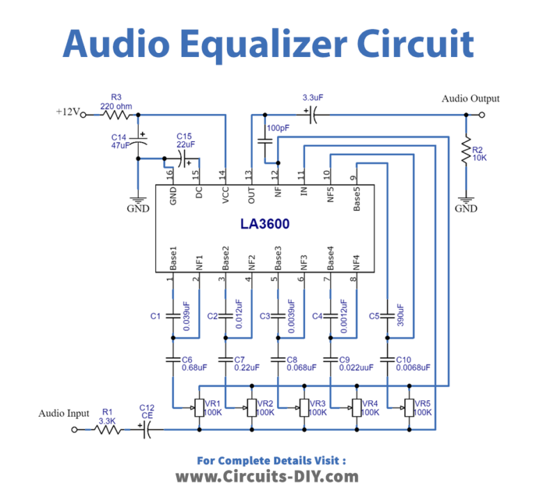
Audio Equalizer Circuit
Working Explanation
This circuit is designed to work with a 12-volt power source, with capacitors and potentiometers separating five distinct bands. These potentiometers are used to change the output of each band. This circuit takes a single audio input and allows you to divide stereo audio or equalize it using two LA3600 ICs. Potentiometers split the audio input signal and send it to distinct base inputs in the equalization IC. Finally, an internal op-amp amplifies all of the basic inputs, and the output audio signal comes out of pin 13.
Application and Uses
- Audio recording circuits or devices.
- Radio studios.
- In theatrical audio systems.

