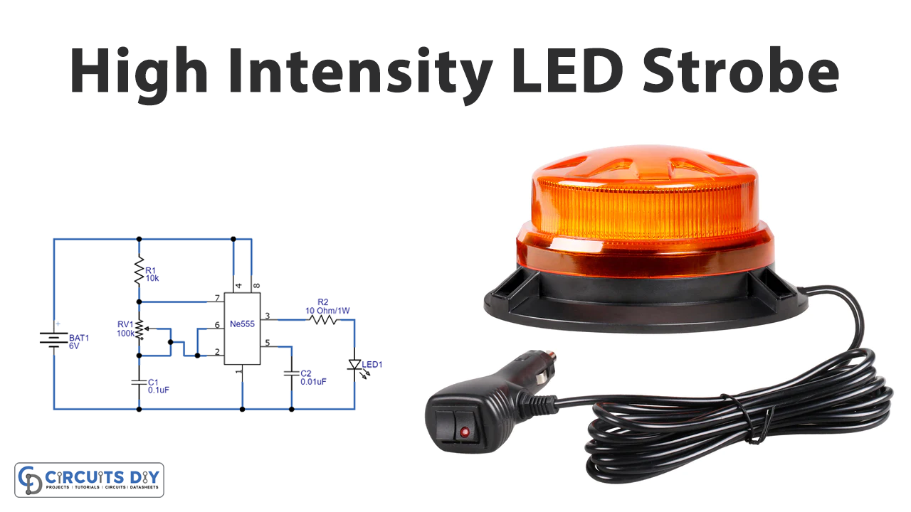
Introduction
If you have seen the planes arriving on the runways, you might have observed that the lane lights get turned ON, it is to be visible in the dark and indicates its presence. If you haven’t seen airplanes, then you might have seen the police automobile. That automobile has a light on its roof, which they turn On while approaching a suspect to indicate its presence so that people make a way for a car. If you still haven’t observed that then you must have seen the lights in some emergency vehicles. These all lights are actually called the strobe light. Thus, it’s not difficult for electronic enthusiasts like you to make the circuit for that light. So, in this tutorial, we are going to ” High Intensity LED Strobe Circuit “

Hardware Components
The following components are required to make LED Strobe Circuit
| S.no | Component | Value | Qty |
|---|---|---|---|
| 1. | IC | NE555 Timer | 1 |
| 2. | LED | 1W | 1 |
| 3. | Potentiometer | 100KΩ | 1 |
| 4. | Capacitor | 0.1µF, 0.01µF | 1,1 |
| 5. | Resistor | 10KΩ, 10Ω/1w | 1,1 |
| 6. | 2-Pin Connector | – | 1 |
| 7. | Battery | 6v | 1 |
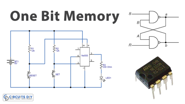
555 IC Pinout

For a detailed description of pinout, dimension features, and specifications download the datasheet of 555 Timer
LED Strobe Circuit
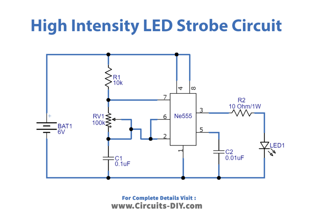
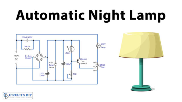
Working Explanation
The 555 is present here in this High Intensity LED Strobe Circuit as an astable multivibrator. It will deliver constant square pulses at the output side. These pulses will turn down the LED On and Off. The time span of this relies on the duty cycle of the square wave. We can change the LED’s blinking rate by adjusting the potentiometer wired in the circuit. The LED has two terminals: cathode and anode. To run this circuit consistently, you can use a LED heat sink with the LED.
Application and Uses
- In aircraft, to show their presence.
- In police automobiles, and in emergency vehicles.
- Also, for entertaining purposes.