For any device or circuit, over and under voltages are harmful. Under voltages can generate light flickers while overvoltages can damage the whole device. Understand this by the example of motor, a motor may get burned because of low running voltages or because of high voltages. So, we comprehended that both the higher voltages and the lower voltages can do a greater amount of harm to any circuit. Hence, every device needs a voltage protection circuit that can indicate and protect the devices from high or low voltage. Coming towards the reverse protection circuit, reverse voltage protection circuits prevent the electronic devices and circuits from reverse polarity voltage that is applied at the input terminals. To understand this all, in this tutorial, we are going to make an “Over Voltage and Reverse Voltage Protection Circuit”
Hardware Required
Circuit Diagram
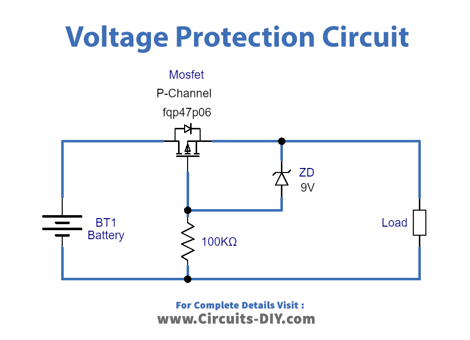
Working Explanation
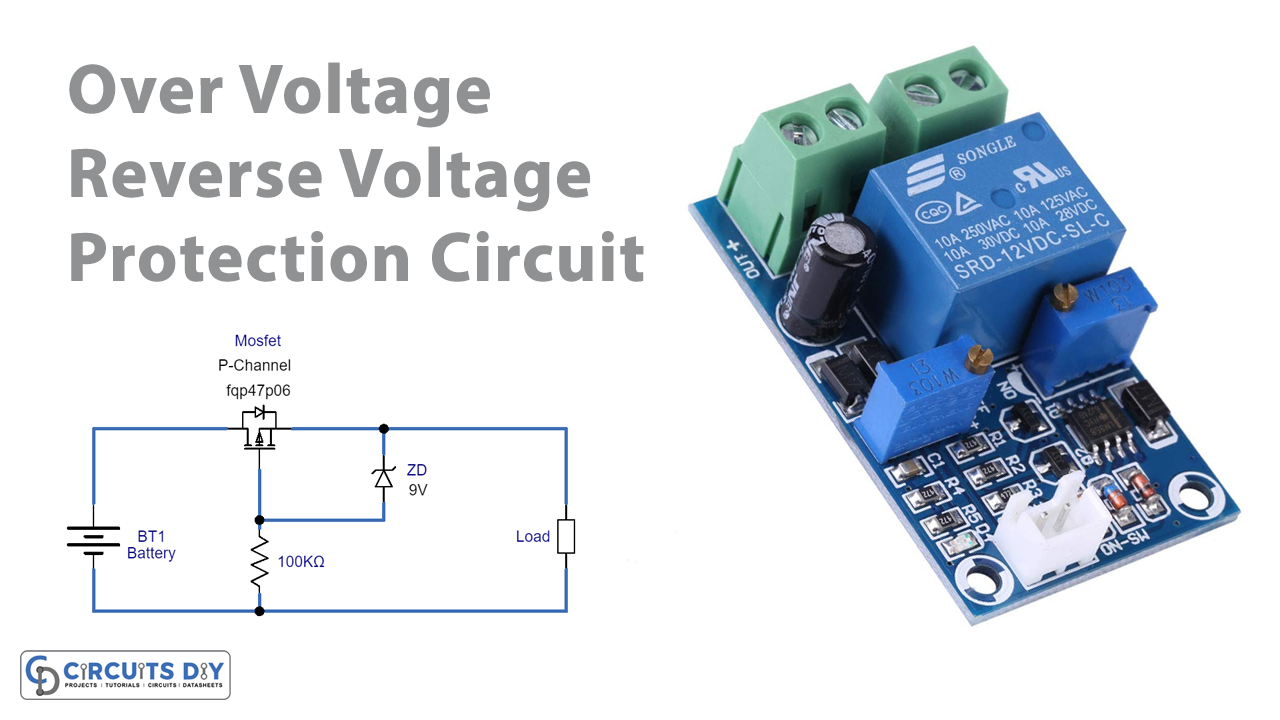
In this Over Voltage and Reverse Voltage Protection Circuit, when you apply input supply to load at the right polarity, the wired MOSFET provides voltage supply to load and the Zener diode which is working as a forward-biased diode. So, when reverse voltage happens the holes of MOSFET start to flow towards negative supply and therefore create a barrier between MOSFET’s drain and the source terminal. Consequently, there would be no supply to flow to the load. In other words, you can say that when the voltage increases beyond 9V, Zener breakdown occurs in the Zener diode and regulates the voltage to 9V and provides the target load.
Application and Uses
- It can be used in power supply circuits.
- In automation systems.
- Circuit breakers, etc.

