Introduction
In many electrical circuits, no voltage controllers are present there, hence if there is any change in the input voltage, it would definitely be expressed or appear at the output. These types of circuits are mostly used for LED lights, DC motors, etc. Thus, we can say that unregulated voltage allows variation on the output side. But, for, any electronic devices like laptops, televisions, etc, these variations can be harmful because they can cause temperature variation, poor regulation, etc.
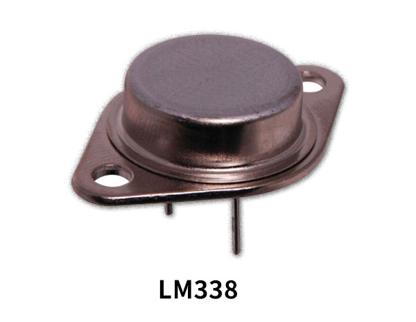
So to overcome this circuits called voltage regulators are used. It reduces the ripples and fluctuations in the voltages. Hence, to understand all of this, in this tutorial, we have decided to make an “Adjustable Voltage Regulator Circuit Using LM338”
Hardware Components
The following components are required to make an Adjustable Voltage Regulator Circuit
| S.no | Component | Value | Qty |
|---|---|---|---|
| 1. | IC | LM338 | 1 |
| 2. | 2-Pin Connector | – | 1 |
| 3. | Diode | 1N5821 | 1 |
| 4. | Inductor | 7LTX17.5µH | 1 |
| 5. | Electrolyte Capacitor | 10µF/25V, 4.7µF/25V | 1,1 |
| 6. | Resistor | 120Ω | 1 |
| 7. | Variable Resistor | 1K | 1 |
| 8. | Diode | 1N4007 | 2 |
LM338 Pinout
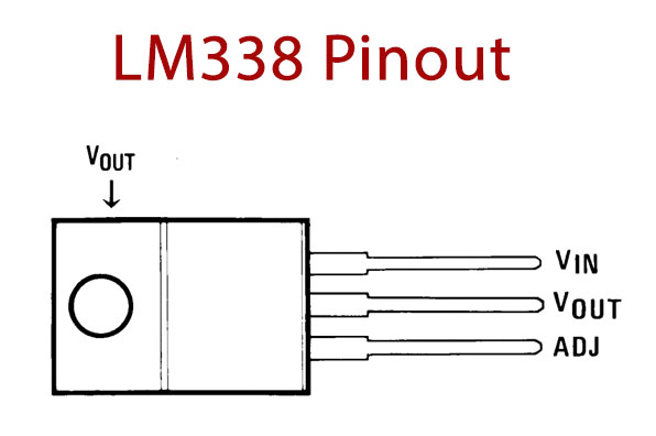
For a detailed description of pinout, dimension features, and specifications download the datasheet of LM338
Adjustable Voltage Regulator Circuit
Working Explanation
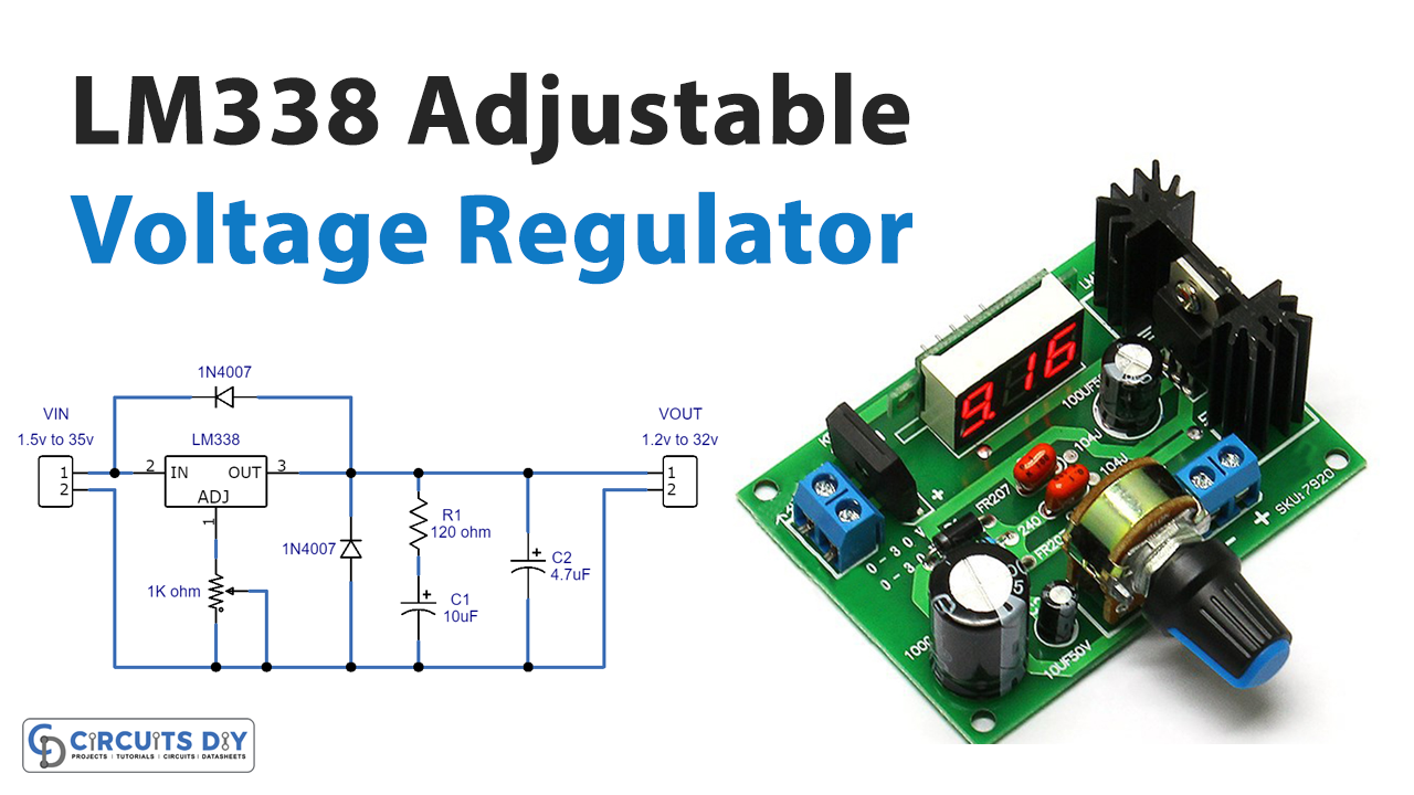
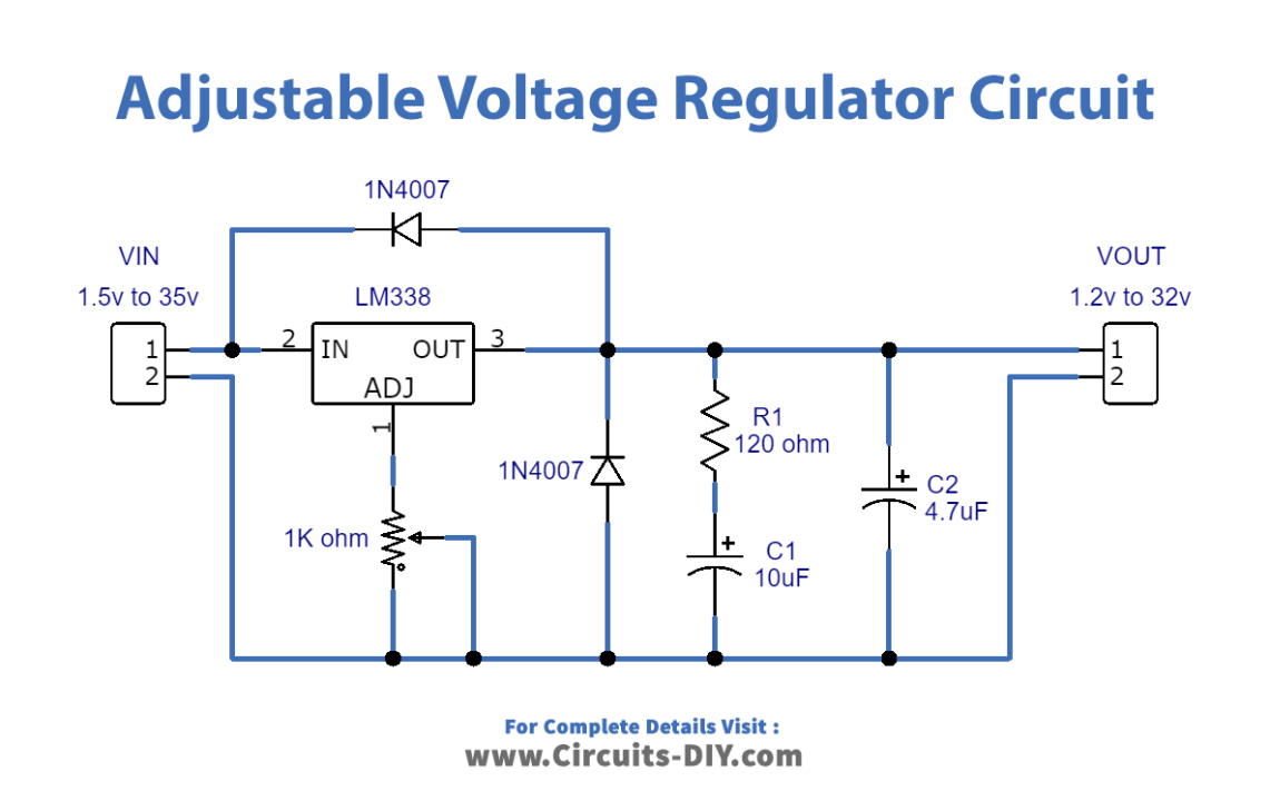
To make this Adjustable Voltage Regulator Circuit we have used the LM338 IC, having three terminals. The unregulated supply is provided at pin 3 of an IC. The potentiometer is wired at pin 1. This potentiometer together with the resistor R1 decides the output voltage. Changing the potentiometer changes the regulated voltage at the output. Diodes d1 and D2 are there to absorb the spikes and protect the whole circuit. In other words, they are utilized as the reverse protection components. C1 is the bypass capacitor. adjustable voltages can be observed at the output capacitor C2.
Application and Uses
- In power supply circuits.
- In many electronic devices like laptops, etc.

