Introduction
In electrical circuits and mechanical machines, the motor performs an influential role. Motors like DC motors, servo motors, and stepper motors are regularly a part of every other machine and hence they are highly used in industrial, automotive, and automation applications. Moreover, these motors are also playing a crucial part in robots and therefore adopted for robotics applications. However, the significant element is the controlling of these motors.
For this reason, there are many different types of drivers which are available in the electronic market. One of the most commonly used drivers is L293D H Bridge Motor Driver. So, in this tutorial, we are going to Make “H-Bridge Motor Driver Circuit L293D”

Hardware Components
The following components are required to make H Bridge Motor Driver Circuit
| S.no | Component | Value | Qty |
|---|---|---|---|
| 1. | IC | L293D | 1 |
| 2. | Diode | 1N4001 | 4 |
| 3. | 3 Pin Connector | – | 1 |
| 4. | 2 Pin Connector | – | 4 |
L293D IC Pinout
For a detailed description of pinout, dimension features, and specifications download the datasheet of L293D
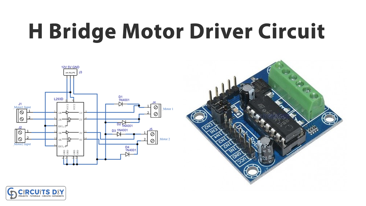
H Bridge Motor Driver Circuit

Working Explanation
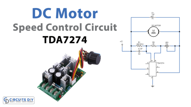
H-Bridge Motor Driver Circuit includes the dual-channel L293D drivers that allow the controlling of two motors. The driver has Vcc pins that allow 5 to 35V. Enable pins are there to control the speed. 1A and 2A are the input for motor 1, while 1Y and 2Y are the output of motor 1. In the same way, 3A and 4A are input for motor two, and 3Y and 4y are its output which drives motor 2. When you connect this circuit according to the diagram given above and give a power supply to that, the motors start to rotate. This circuit can also be interfaced with the Arduino to control the speed of the motors.
Application and Uses
- In automation applications.
- In automotive circuits
- To drive different types of motors.
- In robotics.