The Simple fire alarm circuit is highly sensitive but inexpensive. A sensitive Fire Alarm circuit gives an audio-visual buzzer sound whenever any kind of fire or smoke is detected in the air or an environment. Fire has many forms such as radiation heat form, and smoke detectors. Depending on these types a sensor that matches an application is selected. So, most of the circuits are expensive and difficult to buy. An Infrared Light sensor, on the contrary, is highly sensitive and easy to use. It is almost 100% efficient.

Hardware Components
The following components are required to make a Fire Alarm Circuit
| S. NO | Component | Value | Qty |
|---|---|---|---|
| 1. | Breadboard | – | 1 |
| 2. | Battery | 9v | 1 |
| 3. | Connecting Wires | – | 1 |
| 4. | IR-LED | – | 1 |
| 5. | LED | 5mm | 1 |
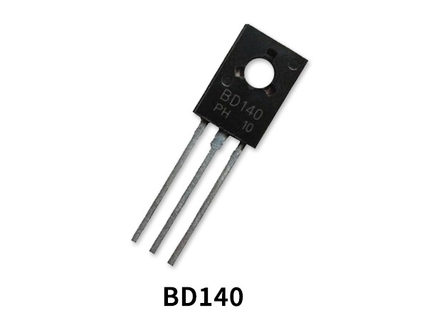
| 6. | PNP Transistor | BD140 | 1 |
| 7. | Buzzer | – | 1 |
| 8. | Resistors | 10k, 100 ohm | 1,1 |
BD140 Pinout

For a detailed description of pinout, dimension features, and specifications download the datasheet of BD140
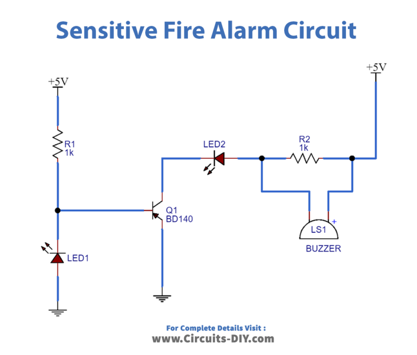
Circuit Diagram

Working Explanation
An IR sensor is a device that detects infrared radiation falling on it. The heart of the sensitive fire alarm circuit is an infrared transmitter and infrared receiver. In normal operating conditions when infrared light is shining from the infrared transmitter from the infrared receiver it will have low impedance. So the voltage at the base will be low and the transistor will not work. In case when a fire is observed an infrared beam will not be able to pass to a receiver. The resistance of the receiver will rise up and the voltage at the base will be positive causing an alarm to activate.
Application
- Industries
- Hospitals
- Banks


