Introduction
Motors have greater use in engineering, either the DC motor, a servo motor, or a stepper motor, industries cannot operate without motors. And, just not industrial machines, these motors are also used at the consumer, and robotics side. So we have decided to discuss one of those motors known as a stepper motor. So, in this tutorial, we are going to interface ” 28BYJ-48 Stepper Motor with Arduino UNO”. Stepper motors get their name from the fact that each electrical pulse causes the motor to move one step forward. Thus, in the stepper motor, a pulsed electrical current is converted into a precise one-step which is controlled by a stepper motor driver. A driver controls stepper motors by sending pulses into the motor, which causes it to rotate.
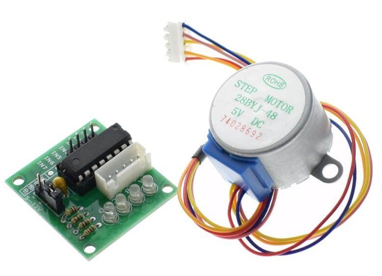
Talking about the driver circuit, we are using the ULN2003 Driver for this tutorial to control the 28BYJ-48 stepper motor. So, before running into the circuit, let’s discuss both of the following components.
An Overview of ULN2003 Driver
A ULN2003 module uses the ULN2003 IC, which is used to operate 4-phase, 5-wire stepper motors on the ULN2003 Stepper Motor Driver Board. The board features a connector that properly matches the motor wires, making it very simple to attach the motor to the board. Four control inputs, as well as power supply connectors, are also available. Four LEDs on the board indicate activity on the four control input lines (indicating stepping status). An ON/OFF jumper is also included on the PCB to isolate power to the stepper Motor.
Pinout of Module
| Pin Number | Pin Name | Description |
| 1 to 7 | Input 1 to Input 7 | Seven Input pins of Darlington pair, each pin is connected to the base of the transistor and can be triggered by using +5V |
| 8 | Ground | Ground Reference Voltage 0V |
| 9 | COM | Used as test pin or Voltage suppresser pin (optional to use) |
| 10 to 16 | Output 1 to Output 7 | Respective outputs of seven input pins. Each output pin will be connected to the ground only when its respective input pin is high(+5V) |
An Overview of 28BYJ-48 Stepper Motor
The 28BYJ-48 Stepper motor has a four-coil unipolar configuration with each coil rated at +5V, making it simple to control with any basic microcontroller. These motors are widely found in DVD players, motion cameras, and other similar devices. These motors can imply a high level of control. However, because these motors only run on 5V, they can’t deliver a lot of torque.
Hardware Required
| S.no | Components | Value | Qty |
|---|---|---|---|
| 1 | Arduino UNO | 1 | |
| 2 | USB Cable Type A to B | 1 | |
| 3 | IC | ULN2003 | |
| 4 | Jumper Wires | – | |
| 5 | Stepper Motor | 28BYJ-48 | 1 |
| 6 | Adapter | 5v | 1 |
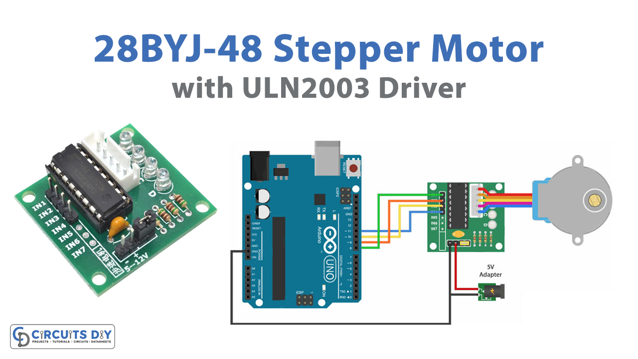
Circuit Diagram

Connection Table
| Arduino | 28BYJ-48 Stepper Motor |
|---|---|
| GND | GND |
| 5V | VCC |
| D8 | IN 1 |
| D9 | IN 2 |
| D10 | IN 3 |
| D11 | IN 4 |
Arduino Code
//Includes the Arduino Stepper Library
#include <Stepper.h>

// Defines the number of steps per rotation
const int stepsPerRevolution = 2038;

// Creates an instance of stepper class
// Pins entered in sequence IN1-IN3-IN2-IN4 for proper step sequence
Stepper myStepper = Stepper(stepsPerRevolution, 8, 10, 9, 11);

void setup() {
	// Nothing to do (Stepper Library sets pins as outputs)
}

void loop() {
	// Rotate CW slowly
	myStepper.setSpeed(100);
	myStepper.step(stepsPerRevolution);
	delay(1000);

	// Rotate CCW quickly
	myStepper.setSpeed(700);
	myStepper.step(-stepsPerRevolution);
	delay(1000);
}
Working Explanation
To Control the 28BYJ-48 Stepper Motor with Arduino UNO, connect the circuit according to the circuit diagram or follow the connection table. Then write the above-given code in Arduino IDE, and upload that in the Arduino UNO. Now, you will observe the rotation of motors according to your code. It first moves in the clockwise direction to complete the prescribed steps at the defined speed then will move in the anti-clockwise direction at the same speed. Hence this is how the circuit works.
Code Explanation
- At first, we have included the stepper motor library. Then, we defined the content stepsPerRevolution which holds the integer number of steps that the motor would take to complete per revolution. Then we created an instance of stepper library myStepper with a sequence of pins 8, 10, 9, and 11. This is because the 28BYJ-48 stepper motor has a step sequence of IN1-IN3-IN2-IN4.
- Since the stepper library has already set the input/output pins as output, therefore, there’s no need to write anything on void setup.
- In the void loop, we have used the setSpeed() function to set the speed of the motor. Then, to tell the motor how many steps to rotate we have used step() functions. So, to rotate clockwise, in their brackets we write stepsPerRevolution in which we have already defined the number before. And, to rotate the motor anti-clockwise, we write – stepsPerRevolution in the brackets. We have also given some delay between both rotations.
Applications and Uses
Stepper motors have greater use in different industries, and therefore this circuit can be utilized at so many trades. For example:
- In robotics, to convert electrical pulse into angular movements, or steps.
- Pulling filament into the extruder in a 3D printer.
- In CNC machines, to transform nonlinear input into linear movement.

