Introduction
To drive the transmission lines, the designers build the circuit, called the audio line driver. It is used in electronic amplifier circuits. Mainly, utilized in the digital system to establish the communication between digital signals and cables. An analog system essentially assists to drive the line-level analog signals. For instance, it can support the music player to connect with the speaker. So, this article is about designing the Audio line driver.
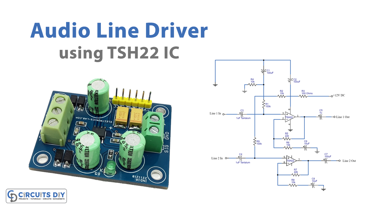
The circuit uses the high-performance dual operational amplifier IC. The circuit can drive 600 ohms of impedance at 1KHz of the frequency with very little distortion. Moreover, the gains of the circuit can be set using the resistors wired into the circuit. The preferable load would be at least 100 ohms so that there would be no stability issues.
Hardware Required
| S.no | Component | Value | Qty |
|---|---|---|---|
| 1. | IC | TSH22 | 1 |
| 2. | Capacitor | 10uf, 100uf | 2, 4 |
| 3. | Ceramic Capacitor | 1uF | 2 |
| 4. | Resistor | 100 ohms, 10k, 22k, 100k | 1, 4, 2, 2 |
| 5. | Power Supply | 12V | 1 |
Circuit Diagram of Audio Line Driver

Working Explanation of Audio Line Driver
In this circuit, we have used two amplifiers of an IC. Both are working as non-inverting opamps. The first amplifier takes the input from line 1. And, the second amplifier takes the input from line 2. The positive voltage is pulled through R1 and R9 for the first and second amplifiers respectively. R5 and R6 are used to set the gain of line 1. Similarly, R7 and R8 are used to set the gain of line 2.
Application and Uses
- In digital systems.
- To drive line-level signals.
- To connect audio stereo devices with the speaker.