Introduction
To get a better gain, bandwidth, slew rate, stability, output impedance, etc, amplifiers use the cascade configuration. In short, Cascode Amplifier Circuit is a two-stage amplifier circuit. Moreover, it contains the common-emitter stage feeding the common-base stage. But, the most important factor for using this configuration is to increase the bandwidth. Because better bandwidth decreases miller’s effect. Thus, to understand cascading, one must need to understand the Miller effect. So, what is the Miller effect?
Certainly, miller’s effect is the multiplication of stray components. Hence, increases the input capacitance. However, an increase in input capacitance can increase the lower cut-off frequency. As a result, it reduces the bandwidth. Since we want an improved bandwidth. Therefore, using the cascade method to improve the amplifier circuit
Hardware Components
The following components are required to make Cascode Amplifier Circuit
| S.no | Component | Value | Qty |
|---|---|---|---|
| 1. | Breadboard | – | 1 |
| 2. | Resistors | 330 ohm, 3.9K, 30K, 50K, 10M | 1 |
| 3. | Capacitor | – | 2 |
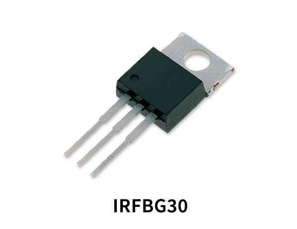
| 4. | FET | IRFBG30 | 2 |
| 5. | Input Supply | – | 1 |
IRFBG30 Pinout
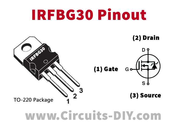
For a detailed description of pinout, dimension features, and specifications download the datasheet of IRFBG30
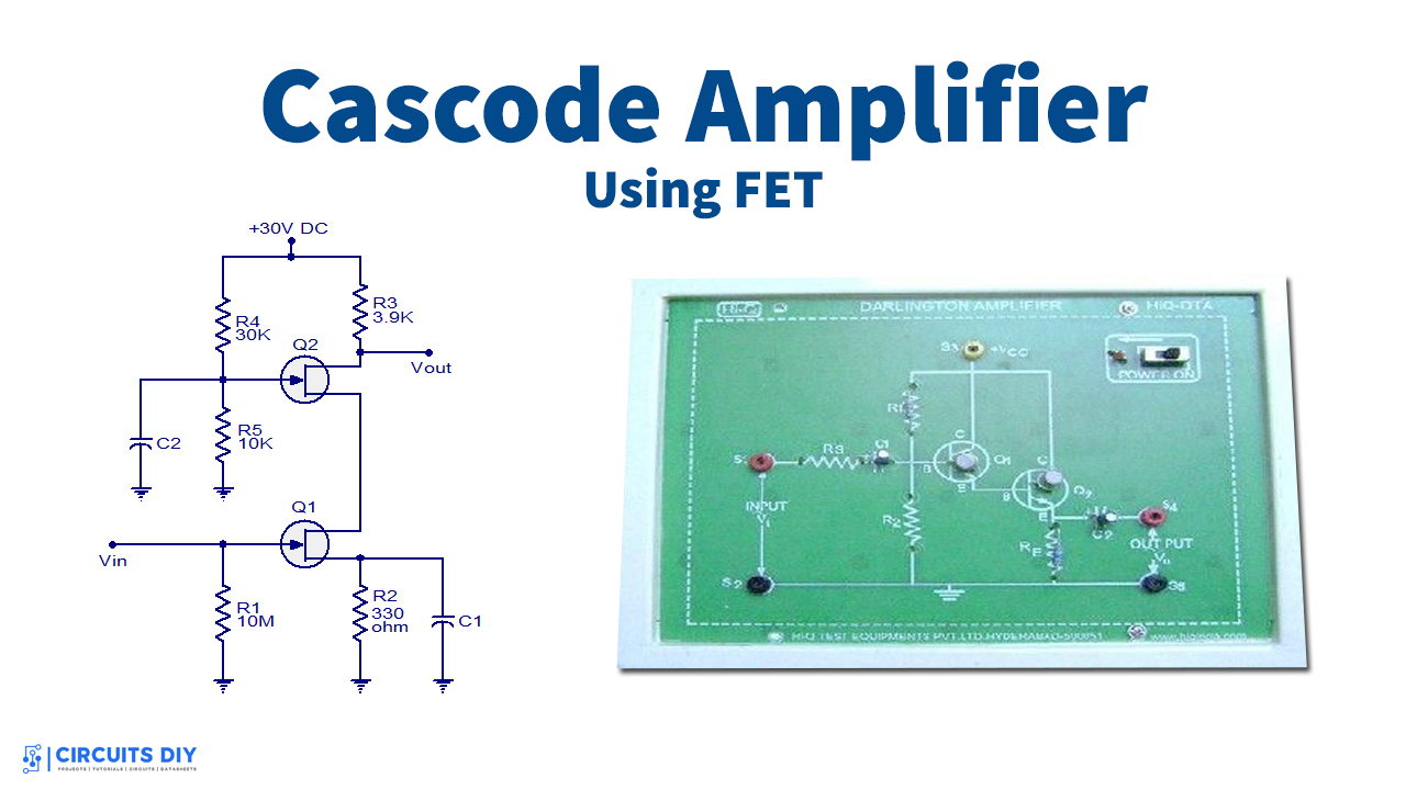
Cascode Amplifier Circuit
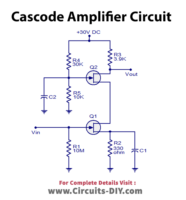
Working Explanation
There are two amplifiers in the circuit. Firstly, the input stage consists of common source FET. That is, the source is grounded. Further, the second stage contains the common gate FET. To sum up, we can say that the first stage of the circuit drives the second stage. Since the gate of the second stage is grounded. Therefore, the voltage at the drain of Q1 and voltage at the source of Q2 is almost the same. This means, that Q2 gives low input resistance to Q1. In conclusion, this reduces the miller effect and increases the bandwidth. Moreover, the lower gain of Q1 does not affect the overall gain of the circuit. Because Q2 compensates for the loss and increases the overall gain.
Application and Uses
- Used in the RF tuners
- Also, for the modulation techniques
- Moreover, to improve the performance of analog circuits

