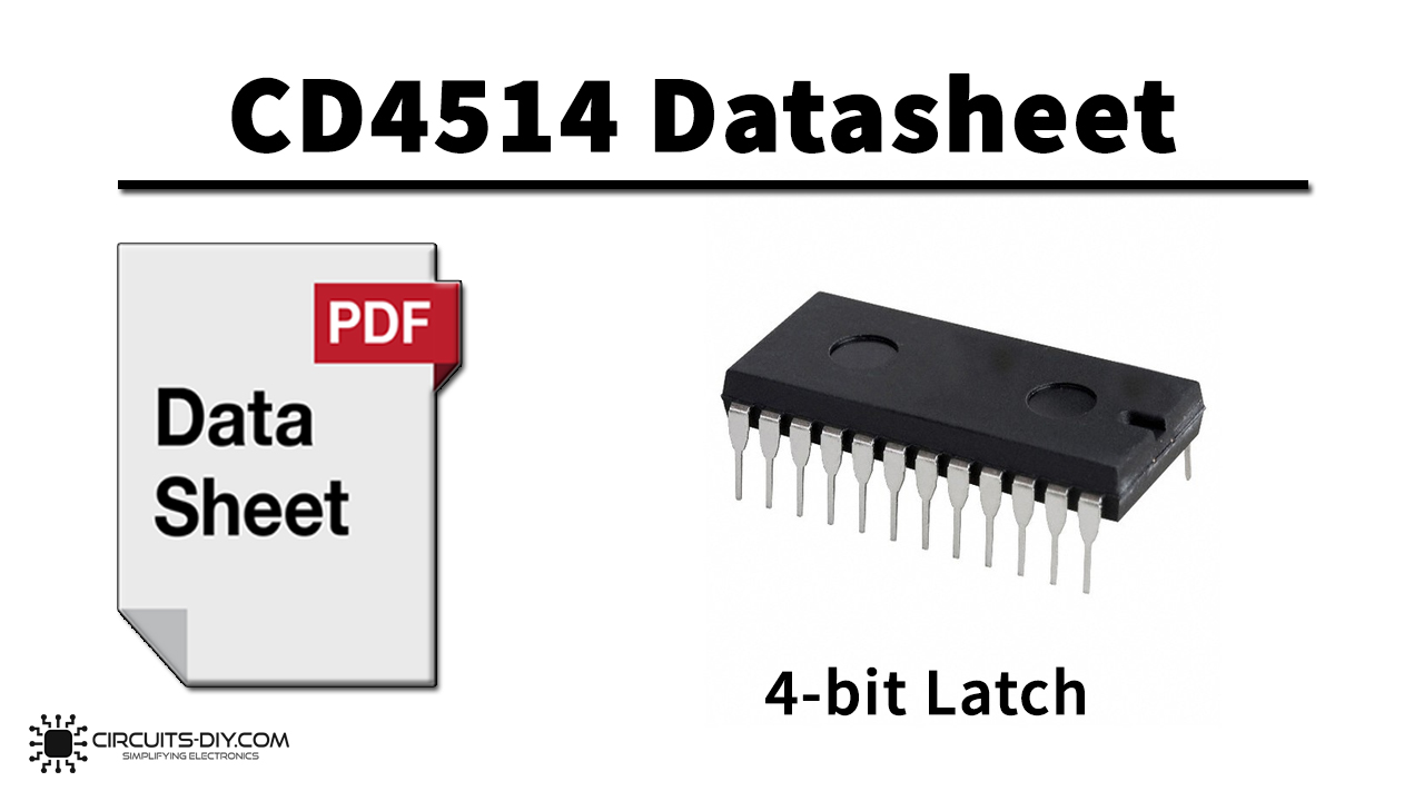
The CD4514BC is a 4-to-16 line decoders / latch. This circuit is primarily used in decoding applications where low power dissipation and/or high noise immunity is required. The CD4514BC presents a logical “1” at the selected output. The input latches are R–S type flip-flops, which hold the last input data presented prior to the strobe transition from “1” to “0”. The IC CD4514 is smaller in size and it has a much faster speed which makes it reliable in every kind of device.
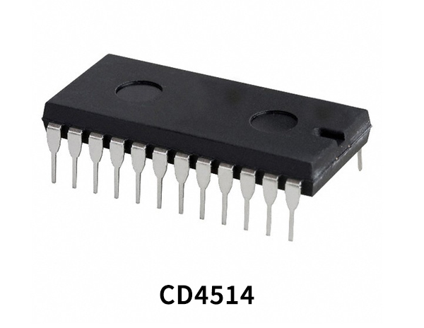
What is Line Decoder?
A line decoder/demultiplexer is a combinational logic circuit & an integral part of todays consumer scale electronics. It is designed to switch one common input line to one of several separate output lines. So, A demultiplexer converts a serial data signal at the input to a parallel data at its output lines.
CD4514 Key Features
- Wide supply voltage range: 3.0V to 15V
- High noise immunity: 0.45 VDD (typ.)
- Low power TTL: fan out of 2
- compatibility: driving 74L
- Low quiescent power dissipation:
- 0.025 µW/package @ 5.0 VDC
- Single supply operation
- Input impedance = 1012Ω typically
- Plug-in replacement for MC14514, MC14515
CD4514 Pinout
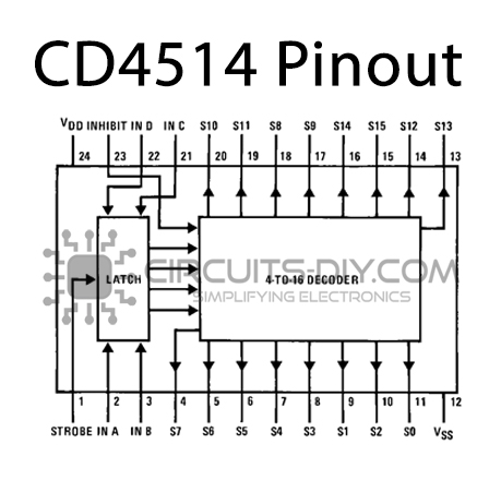
| Pin No | Pin Name | Description |
|---|---|---|
| 1 | STROBE | Strobe Pin |
| 2 | IN A | Input Pin A of Line Decoder |
| 3 | IN B | Input Pin B of Line Decoder |
| 4 | S7 | Output Pin 7 of Line Decoder |
| 5 | S6 | Output Pin 6 of Line Decoder |
| 6 | S5 | Output Pin 5 of Line Decoder |
| 7 | S4 | Output Pin 4 of Line Decoder |
| 8 | S3 | Output Pin 3 of Line Decoder |
| 9 | S1 | Output Pin 1 of Line Decoder |
| 10 | S2 | Output Pin 2 of Line Decoder |
| 11 | S0 | Output Pin 0 of Line Decoder |
| 12 | VSS | Source Supply |
| 13 | S13 | Output Pin 13 of Line Decoder |
| 14 | S12 | Output Pin 12 of Line Decoder |
| 15 | S15 | Output Pin 15 of Line Decoder |
| 16 | S14 | Output Pin 14 of Line Decoder |
| 17 | S9 | Output Pin 9 of Line Decoder |
| 18 | S8 | Output Pin 8 of Line Decoder |
| 19 | S11 | Output Pin 11 of Line Decoder |
| 20 | S10 | Output Pin 10 of Line Decoder |
| 21 | IN C | Input Pin C of Line Decoder |
| 22 | IN D | Input Pin D of Line Decoder |
| 23 | INHIBIT | Inhibit Pin |
| 24 | VDD | Drain Supply |
Application
- Digital Multiplexing
- Address Decoding
- Hexadecimal/BCD Decoding
- Program-counter Decoding
- Control Decoder
CD4514 Datasheet
You can download the datasheet forCD4514 4-bit Latch/4-16 Line Decoder IC from the link given below:
See Also: 74LS122 Retriggerable Monostable Multivibrator IC | 74LS109 Dual JK Positive Edge-Triggered Flip-Flop IC | 74LS92 4-Bit Divide By Twelve Binary Counter IC

