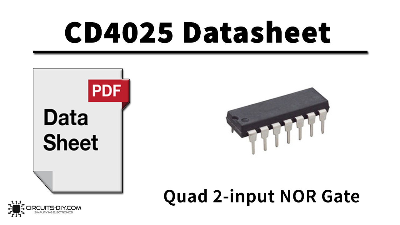
CD4025 consists of three NOR gates with 3 inputs and a single output. The IC is constructed by using the complementary MOS (CMOS) technology, integrated with p-type and n-type enhancement mode transistors. The IC is always available in a 14 – pin hermetically sealed dual in line package (DIP). The output of the IC always comes in TTL, which makes it easy to interface with other TTL, CMOS, and NMOS devices. The IC offers many features such as high noise immunity and low power dissipation. All inputs are protected against static discharge with diodes to VDD and VSS.

What is NOR Gate?
An OR gate followed by a NOT gate in a cascade is called a NOR gate. The inclusive NOR (Not – OR) gate has an output that is normally at logic level “1” and only goes “LOW” to a logic level “0” when any of its inputs are at logic level “1”. The Logic NOR Gate is the reverse or complementary form of the inclusive OR gate.
CD4025 Key Features
- Wide supply voltage range 3.0V to 15V
- High noise immunity 0.45 VDD (typ.)
- 5V –10V parametric ratings
- Low power
CD4025 Pinout

| Pin No | Pin Name | Description |
|---|---|---|
| 1 | A1 | input 1 of NOR gate 1 |
| 2 | B1 | input 2 of NOR gate 1 |
| 3 | A2 | input 1 of NOR gate 2 |
| 4 | B2 | input 2 of NOR gate 2 |
| 5 | C2 | input 3 of NOR gate 2 |
| 6 | Q2 | output of NOR gate 2 |
| 7 | VSS | source supply |
| 8 | C1 | input 3 of NOR gate 1 |
| 9 | Q1 | output of NOR gate 1 |
| 10 | Q3 | output of NOR gate 3 |
| 11 | C3 | input 1 of NOR gate 3 |
| 12 | B3 | input 2 of NOR gate 3 |
| 13 | A3 | input 3 of NOR gate 3 |
| 14 | VDD | Drain supply |
Application
- Cell phone
- Computing
- STB
- LCD TV
- Industrial controllers
CD4025 Datasheet
You can download the datasheet for CD4025 Triple 3-Input NOR Gate IC from the link given below:
See Also: CD40193 8-bit Up/Down Binary Counter – Datasheet | CD4512 8-Channel Data Selector – Datasheet | CD4503 Tri-state Hex Buffer – Datasheet

