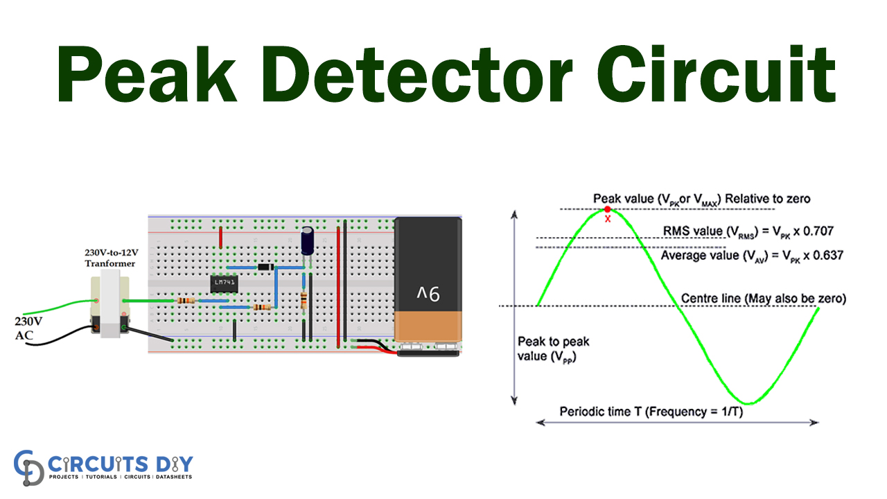
The Peak Detector Circuit is generally used in a dynamically shifting waveform to locate the peak amplitude. Therefore, in this DIY tutorial, we will gonna show you how to make a Peak detector circuit with just a few electronics components. Although, in sound measurement systems, peak detectors are typically used to locate the highest sound frequency in a given location or position. Meanwhile, it helps to calculate the maximum loudness level there.
Furthermore, there are many implementations of this particular circuit in which a Peak Detector Circuit is used. However, we may not even require complicated components of electronics for a Simple Peak Detector Circuit. We generally utilize a diode and a capacitor to create a single Peak Detector circuit.

Hardware Component
The following components are required to make Peak Detector Circuit
| S.no | Component | Value | Qty |
|---|---|---|---|
| 1. | Oscilloscope | – | 1 |
| 2. | Op-amp IC | LM741 | 1 |
| 3. | Diode | 1N4007 | 1 |
| 4. | Resistor | 10k | 3 |
| 5. | Capacitor | 4.7uf | 1 |
| 6. | Breadboard | – | 1 |
| 7. | Jumping Wires | – | 1 |
LM741 Pinout

For a detailed description of pinout, dimension features, and specifications download the datasheet of LM741
Peak Detector Circuit

Circuit Operation
The circuit operation of the peak detector circuit is however pretty simple. Meanwhile, the op-amp output is lower in the first negative half step to reverse the diode. Therefore the capacitor holds the optimum value of the input signal until the diode is biassed again. The op-amp is open in this reversed diode state and is saturated, so the capacitor continues to discharge to the RL. That is why in the negative period of the signal, you can see the falling pitch.
Therefore, below is the output waveform of the op-amp based on the peak detector circuit.
Applications and Uses
Generally, the optimum value (max) of the input signal is calculated by Peak Detectors circuits. It holds for an indefinite cycle the maximum value of input voltages before reset.


